Boonton 8201 Modulation Analyzer Quick Start User Manual
Page 9
9
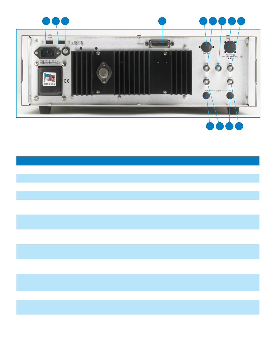
Figure-3: Rear View of 8201 Modulation Analyzer
Table-2: Controls, Displays and Connectors of Back Panel of 8201 Modulation Analyzer (Figure-3)
Control, Indicator or Connector
Index Number
Function
Fuse holder
1
Holds fuse for ac line protection.
Line connector
2
Permits connection of instrument to ac power supply.
Voltage Selector Switch
3
Permits the selection of various ac power supply voltages.
IEEE-488 bus connector
4
Provides a means for connecting the Model 8201 to a system control bus.
IF out connector
5
Provides a means for connecting the intermediate frequency signal to external
test equipment.
FM out connector
6
Provides a means for connecting the demodulated FM signal to external test
equipment.
AM out connector
7
Provides a means for connecting the demodulated AM signal to external test
equipment.
DIST out connector
8
Provides a means for connecting the distortion analyzer signal output to external
test equipment.
EXT REF connector
9
Provides a means for connecting an external 10 MHz frequency standard to the
internal time base circuits.
Optional:
CAL OUT connector
10
Provides a means for connecting the optional 50 MHz,
0 dBm calibrator to the Model 8201 for level calibration.
RF IN connector
11
Optional RF input connector, used to apply an external carrier signal.
AUDIO OUT connector
12
Provides a means for connecting the modulation signal to external filters or pro-
cessing circuits.
AUDIO IN connector
13
Provides a means for connecting an external audio signal to the internal baseband
processing circuits.
12
8
13
9
2
3
1
4
10
5
6
11
7