American Fibertek RR-94085SL User Manual
Page 6
6
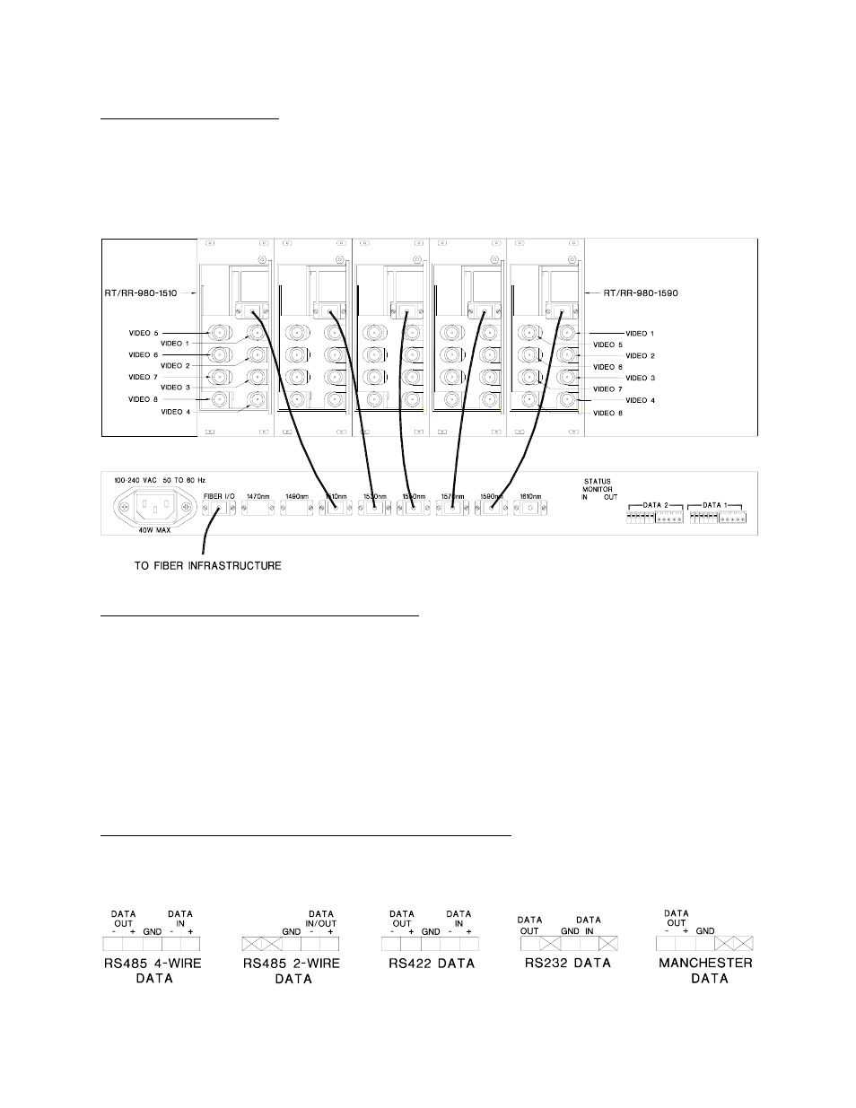
FIBER CONNECTIONS
The fiber optic connection to the user’s infrastructure is made via a SC connector located at the
back of the CDWM unit next to the power input. Be sure to allow sufficient room for the required
minimum bend radius of the fiber cable used. SC patchcords are supplied for the intra-fiber
connections between the CWDM and each of the 980 series units. The wavelength listed for
each port on the CWDM must correlate with the wavelength listed on the 980 series unit to
which that port is attached.
VIDEO INPUT / OUTPUT CONNECTIONS
Video input and output connections are located on the rear of the 980 series units. A BNC
connector is provided for each channel. The video inputs are connected to an appropriate 75
Ω
baseband video source such as a camera or a video recorder output. The 75
Ω video outputs
can be looped through typical baseband video inputs of switchers, recorders and other
equipment as required. For proper operation, the outputs must be terminated with 75
Ω. For
optimum performance the video cables should be the shortest length of coax practical.
The location of a video input to the RT-94085SL will be mirrored as a video output at the RR-
94085SL. For example, the Channel 2 video input on the RT-980-1550 will become the Channel
2 video output on the RR-980-1550 after traveling across the fiber infrastructure.
RT-94085SL DATA INPUT / OUTPUT CONNECTIONS
Data input and output connections are made via terminal blocks on the back of the MTX-
CDWM-8-MPD unit. See the drawings below for proper orientation of the input and output
connections for each of the two data channels. Please note that the far right pin on each
connection drawing corresponds with the far right terminal block pin on the unit.