STEINEL IS 360 User Manual
Page 3
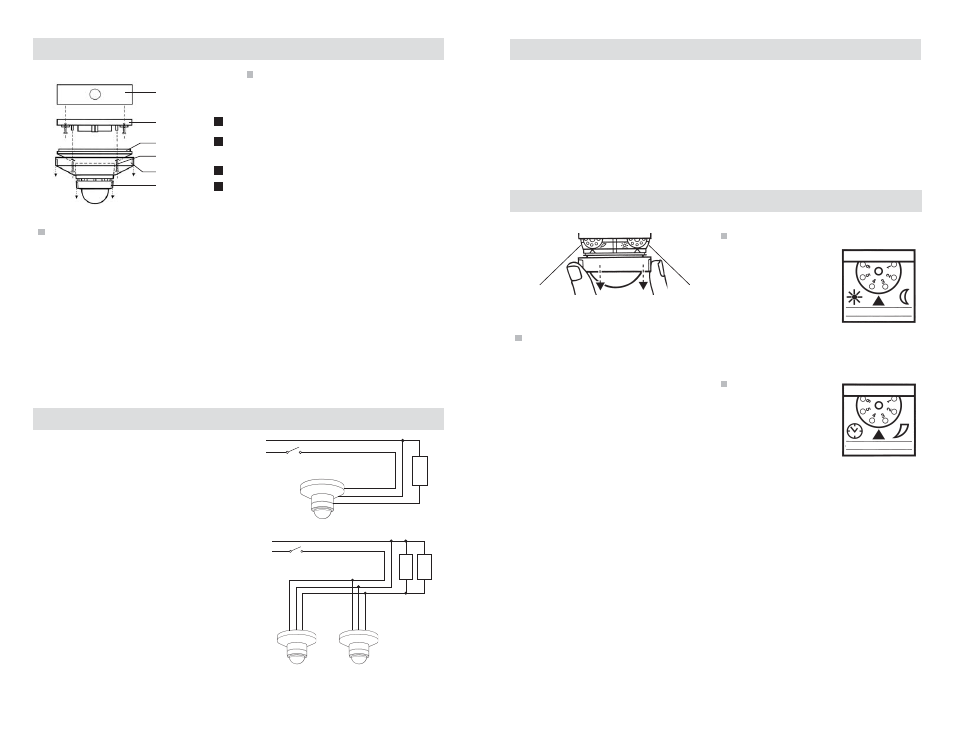
Setup & Commissioning
Wiring
Operation
L
O
A
D
LINE (BLACK)
NEUTRAL
Local OFF
Switch (optional)
HOT
NEUTRAL (WHITE)
LOAD (RED)
When installing, make sure power has been
switched off at the breaker and check that
the circuit is dead with a voltage tester. The
leads consist of three wires:
Black L IN = hot wire
Red L OUT = switched hot wire for fi xture
White N = neutral wire. Connect N (white)
with the neutral wire (usually white)
Connect L OUT (red) with the hot wire of the
fi xture (usually black.) Connect L (black)
with the hot wire of the supply lead (usually
black.)
Test mode
• Ensure that the sensor is in test mode.
- set time delay to position 1
(minimum setting of 10 sec).
- set light level to position 1 (light level
function overridden).
• Turn power ON at the circuit breaker
(lights will turn ON). After a warm up
period of up to one minute, lights will
turn OFF if the sensor does not detect
motion.
• Walk in view of sensor, lights should
turn ON. Be still for 10 seconds and
lights should turn OFF.
Light level
The light level feature
allows lighting to remain
OFF during daylight,
regardless of occupancy.
Daytime operation is
at 200 footcandles
(factory setting) with the
adjustment set at position 1. Nighttime
operation, .2 footcandles, is at position 6.
Time delay
Time delay is the period
of time lights remain
on after a space is left
unoccupied. Adjustment
ranges from 10 sec
(factory setting) to 15
min.
After setup and commissioning tests are
complete, adjust the time delay and light
level settings to fi t your application needs.
Light Level
Time Delay
L
O
A
D
L
O
A
D
LINE (BLACK)
NEUTRAL
Local OFF
Switch (optional)
HOT
NEUTRAL (WHITE)
LOAD (RED)
LINE (BLACK)
NEUTRAL (WHITE)
LOAD (RED)
5
.2 - 200 fc
10 sec - 15 min
The IS 360 operates by turning lights on
automatically when occupancy is detected
and off when the space is left vacant and
the time delay has elapsed.
The light level feature keeps lighting
off during daylight hours, regardless of
occupancy.
Adding a wall switch provides a manual
override function. While the switch is ON,
the sensor is in occupancy control mode.
Users can turn the switch OFF at any time
to keep lights OFF.
Mounting
Fastening screw
Placement guidelines
• Intended for surface mounting under
soffi t (exterior) or on ceiling (interior)
• Ideal outdoor placement for the IS 360
is under an overhang
• Detection lens must have a clear,
unobstructed view of detection area
• Ideal mounting height is 8-12 feet
Installation
Ensure use of the correct enclosure and
confi rm power is off at the circuit breaker.
• Remove housing cover. Press the two
indentations on side of housing cover,
turn counter-clockwise and pull.
• Backout the 2 fastening screws;
separate sensor housing from
mounting plate.
• Insert the two rubber plugs into the
mounting plate.
• Place the sensor wires through the
knockout in the center of the mounting
plate and connect electrical wires (see
Wiring).
• Align mounting plate with junction box
and secure with j-box screws.
• Realign mounting plate to sensor
housing; secure with fastening screws.
• Reapply and engage the housing cover.
Housing cover
Decorative ring
Mounting plate
Sensor housing
Junction box
1
2
4
3
4
www.steinel.net
(800) 852-4343
www.steinel.net
(800) 852-4343