Electrical system – Airstream 390 User Manual
Page 94
H
ELECTRICAL SYSTEM
H - 22
SERVICE
CONTROL REPLACEMENT
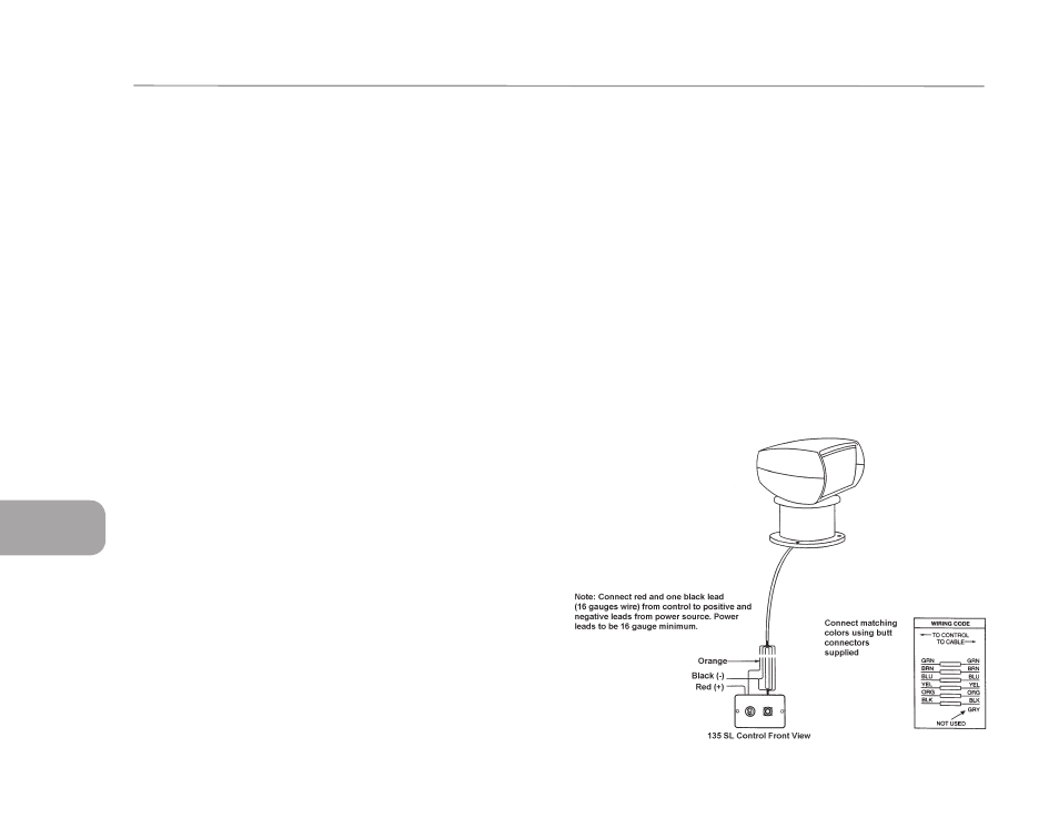
Individual replacement parts are available for the control panel. To replace switches
remove the two (2) screws from front of panel and pull forward, exposing wiring.
1 .To remove directional switch push firmly on the front toggle and remove switch from
back side of panel. Cut wires to the defective switch, and splice wires (with butt
connectors) to the new switch, being sure to match wire colors. Note: Install switch
with yellow wire on top for correct directional aiming.
2. To remove On/Off fuse switch disconnect w-1res to defective switch and pull
forward will gentle rocking motion from backside of panel easing switch out. Install
new switch and secure using clip retainer on backside of control panel. Reconnect
wiring terminals to switch.
BULB REPLACEMENT
Remove four (4) screws and retaining bezel. Pull bulb assembly forward and discon-
nect spade connectors from back of bulb. Reconnect spade terminals to new bulb.
Install bulb and fasten with bezel and four (4) screws.
PARTS LIST
Part No.
Description
18753-0178
Bulb Kit
43990-0000
Directional Switch
18753-0180
On/Off Fuse Switch
64073-0020
Station Selector Switch
60030-0000
Control
45969-1000
12/24 Volt Converter
60023-1000
Upper Housing
60024-1000
Lower Housing
60027-1000
Bass
60035-1000
Bulb Retainer