AquaStar 125B LP User Manual
Page 13
13
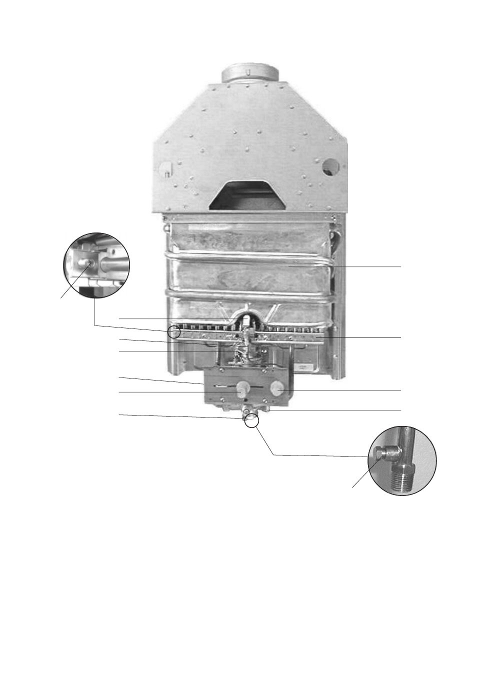
Fig. 11 -
Diagram of AquaStar 125 B
5
11
1
4
9
10
1.
Heat exchanger
2.
Pilot assembly
3.
Burner manifold gas
pressure test nipple
4.
Main gas burner
5.
Pilot gas tubing
6.
Gas valve
7.
Pressure tap screw
location
8.
Gas control slide
9.
Piezo igniter
10.
Water valve
11.
Temperature adjustment
selector
12.
Gas inlet gas pressure
test nipple
3
12
2
6
7
8
This manual is related to the following products: