KAL EQUIP KAL 3840 User Manual
Page 59
1. Connect the capacitive type ignition secondary probe to the CH A input terminal.
2. Connect the CO M input of the test tool to vehicle ground by using a Ground Lead (black) in order to avoid
electrical shock before clamping the secondary probe on the coil secondary lead wire.
3. Clip the secondary probe to the coil secondary lead wire before the distributor.
4. With the Key On, Engine Running (KOER), use the throttle to accelerate and decelerate the engine or drive the
vehicle as needed to make the driveability problem or misfire occur.
5. If the firing line is negative, press to invert the pattern.
6. Make sure that the amplitude, frequency, shape and pulse width are all consistent from cylinder to cylinder. Look
for abnormalities in the section of the waveform that corresponds to specific components.
• Reference Waveform
VEHICLE INFORMATIONS
YEAR
: 1994
MAKE
: Ford
MODEL
: Explorer
ENGINE
: 4.0 L
FUELSYS : Multiport Fuel Injection
PCM_PIN : Cyl #1 Spark Plug wire
STATUS
: KOER (Key On Running)
RPM
: Idle
ENG_TMP : Operating Temperature
VACUUM : 19.5 In. Hg
MILEAGE : 40045
• Troubleshooting Tips
Look for t he drop in t he waveform where the ignition coil begins charging t o stay relatively consist ent, which
indicates consistent dwell and timing accuracy of individual cylinder.
Look for a relatively consistent height on the “arc-over” voltage or firing line. A line that is too high indicates high
resistance in the ignition secondary due to an open or bad spark plug wire or a large spark gap. A line that is too
short indicates lower (than normal) resistance in the ignition secondary due to fouled, cracked, or arcing spark plug
wire, etc.
Look for the spark or burn voltage to remain fairly consistent. This can be an indicator of air-fuel ratio in the cylinder.
If the mixture is too lean, the burn voltage may be higher, and if too rich, the voltage may be lower than normal.
Look for the burn line to be fairly clean without a lot of hash, which can indicate an ignition misfire in the cylinder due
to over-advanced ignition timing, bad injector, fouled spark plug or other causes. Longer burn lines (over 2 ms) can
indicate an abnormally rich mixture and shorter burn lines (under 0.75 ms) can indicate an abnormally lear mixture.
Look for at least 2, preferably more than 3 oscillations after the burn line. This indicate a good ignition coil (a good
condenser on point-type ignitions).
6-67
The secondary POWER/WASTE spark display waveform can be used to test several aspects of EI (or DIS) system
operation. This test can be used to :
1. analyze individual cylinder dwell (coil charging time),
2. analyze ignition coil and secondary circuit performance (from the firing line),
3. locate incorrect air-fuel ratio in individual cylinders (from the burn line), and
4. locate fouled or damaged spark plugs that cause a cylinder misfire (from the burn line).
Generally on modern high energy ignition (HEI) systems, firing voltages should be around 15 kV to beyond 30 kV.
Firing voltages vary based on spark plug gap, engine compression ratio, and air-f uel mixture. On dual spark EI
systems, the WASTE spark is usually much lower in peak voltage than the POWER spark. Close to 5 kV can be
normal.
• Symptoms
No or hard starts, stalls, misfires, hesitation, poor fuel economy
• Test Procedure
NOTE
A Capacitive type ignit ion secondary probe must be used t o t est the ignition
secondary circuit. Connecting t he CH A or CH B leads directly to an ignition
secondary circuit can cause severe damage to the instrument or even personal
injury.
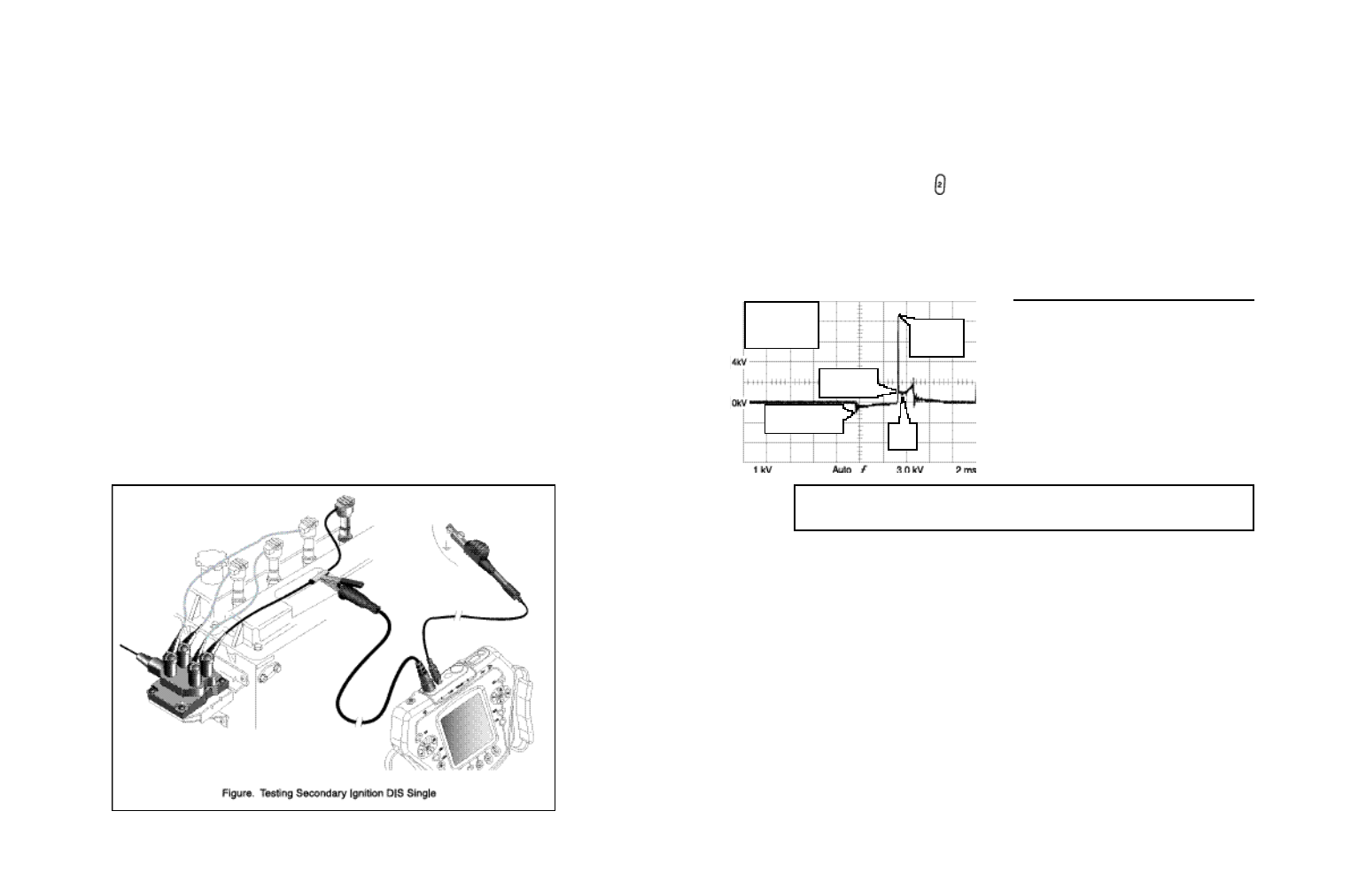
Connect the test leads as displayed by the test tool’s HELP (Test Procedure) and shown in Figure below.
6-66
Look closely to see that the pulse width (dwell) changes when engine load and RPM
changes.
FIRE = 8.53 kV
BURN = 1.30 kV
DUR = 1.36 ms
RPM = 780
spark or burn
voltage
Ignition coil begins
charging here
Burn
line
arc-over
or ignition
voltage