4 rear panel, 4 chapter 1: system introduction – Asus CT5430 User Manual
Page 12
1-4
Chapter 1: System introduction
1.4
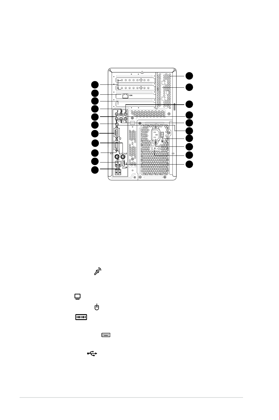
Rear panel
The system rear panel includes the power connector and several I/O ports that
allow convenient connection of devices.
13. Expansion slot covers. Remove these covers when installing expansion
cards.
14. LAN port. This port allows connection to a Local Area Network (LAN) through
a network hub.
15. Expansion slots. Use this slot when installing expansion card.
16. Rear surround speakers. This port connects to a high-definition six-channel
speaker.
17. Side surround speakers. This port connects to a high-definition six-channel
speaker.
18. Microphone port . This Microphone (pink) port connects a microphone.
In 4/6-channel mode, the function of this port becomes Low Frequency
Enhanced Output/Center.
19. VGA port . This port connects a VGA monitor.
20. PS/2 mouse port . This green 6-pin connector is for a PS/2 mouse.
21. COM port
. This port connects a mouse, modem, or other devices that
conforms with serial specification.
22. PS/2 keyboard port . This purple 6-pin connector is for a
PS/2 keyboard.
23. USB 2.0 ports
2.0
. These Universal Serial Bus 2.0 (USB 2.0) ports are
available for connecting USB 2.0 devices such as a mouse, printer, scanner,
camera, PDA, and others.
REAR
S
P
K
LINE
IN
FR
ONT
MIC IN
SIDE
S
P
K
C T
R
B
ASS
14
15
16
17
18
19
20
21
22
23
24
25
26
27
28
29
30
31
32
33
13