Leveling, Clearances, Hard water – A.O. Smith BTN 120 THRU 400/A Series User Manual
Page 7: Air requirements
7
length and width at least 2" greater than the diameter of the
heater and must be piped to an adequate drain. The pan must
not restrict combustion air flow.
LEVELING
If the unit is not level, insert the bolts which were used in crating
into the legs to correct this condition.
CLEARANCES
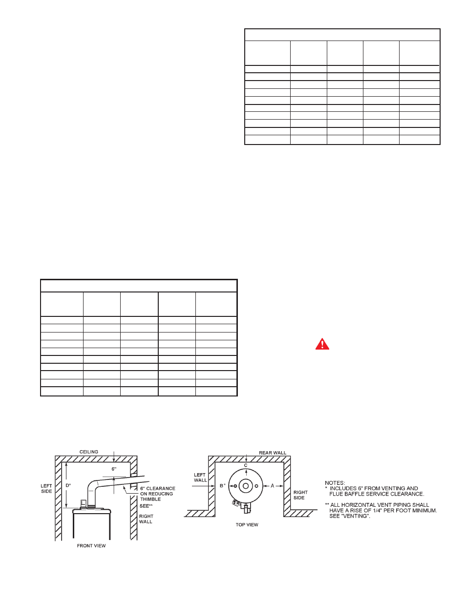
These heaters are approved for installation on combustible
flooring (with Leg Kit #6570-7) in an alcove when the minimum
clearance from any combustion construction are followed as
indicated in figure 5 and Table 4.
In all installations the minimum combustible clearances from
vent piping shall be 6" (152mm). Vent piping passing through a
combustible wall or ceiling must be a continuous run (no joints)
and retain the 6" (152mm) clearance unless an approved
reducing thimble is used.
A service clearance of 24" (610mm) should be maintained from
serviceable parts, such as relief valves, flue baffles, thermostats,
cleanout openings or drain valves.
The units are approved for installation with side, rear and ceiling
clearances as indicated below:
MINIMUM CLEARANCES TO COMBUSTIBLES IN INCHES (mm)
MODEL
”A”
”B”
”C”
”D”
RIGHT
LEFT
BACK
CEILING
SIDE
SIDE
BTN-120
2” (51mm)
2” (51mm)
2” (51mm) 12” (305mm)
BTN-154
2” (51mm)
2” (51mm)
2” (51mm)
12” (305)
BTN-180
2” (51mm)
2” (51mm)
2” (51mm)
12” (305)
BTN-199
2” (51mm)
2” (51mm)
2” (51mm)
12” (305)
BTN-200/A
2” (51mm)
2” (51mm)
2” (51mm)
12” (305)
BTN-250/A
2” (51mm)
2” (51mm)
2” (51mm)
12” (305)
BTN-275/A
2” (51mm)
2” (51mm)
2” (51mm)
12” (305)
BTN-310/A
3” (76mm)
3” (76mm)
3” (76mm)
12” (305)
BTN-366/A 6” (152mm) 6” (152mm)
6” (152mm)
12” (305)
BTN-400/A
3” (76mm)
3” (76mm)
3” (76mm)
12” (305)
TABLE 4
CLEARANCES TO NONCOMBUSTION CONSTRUCTION
MODEL
”A”
”B”
”C”
”D”
RIGHT
LEFT
BACK
CEILING
SIDE
SIDE
BTN-120
0
0
0
12” (305mm)
BTN-154
0
0
0
12” (305mm)
BTN-180
0
0
0
12” (305mm)
BTN-199
0
0
0
12” (305mm)
BTN-200/A
0
0
0
12” (305mm)
BTN-250/A
0
0
0
12” (305mm)
BTN-275/A
0
0
0
12” (305mm)
BTN-310/A
6” (152mm) 6” (152mm) 6” (152mm) 12” (305mm)
BTN-366/A
0
0
0
12” (305mm)
BTN-400/A
0
0
0
12” (305mm)
TABLE 5
HARD WATER
Where hard water conditions exist, water softening or the
threshold type of water treatment is recommended. This will
protect the dishwashers, coffee urns, water heaters, water piping
and other equipment.
See MAINTENANCE section for details of tank cleanout
procedure.
AIR REQUIREMENTS
REFER TO THE LATEST EDITION OF THE "NATIONAL FUEL
GAS CODE" ANSI Z223.1/NFPA 54.
KEEP APPLIANCE AREA CLEAR AND FREE OF COMBUSTIBLE
MATERIALS, GASOLINE AND OTHER FLAMMABLES, VAPORS
AND LIQUIDS.
DO NOT OBSTRUCT THE FLOW OF COMBUSTION OR
VENTILATING AIR.
WARNING
FOR SAFE OPERATION PROVIDE ADEQUATE AIR FOR
COMBUSTION AND VENTILATION. AN INSUFFICIENT SUPPLY
OF AIR WILL CAUSE RECIRCULATION OF COMBUSTION
PRODUCTS RESULTING IN AIR CONTAMINATION THAT MAY
BE HAZARDOUS TO LIFE. SUCH A CONDITION OFTEN WILL
RESULT IN A YELLOW, LUMINOUS BURNER FLAME, CAUSING
CARBONING OR SOOTING OF THE COMBUSTION CHAMBER,
ILLUSTRATION OF MINIMUM COMBUSTIBLE CLEARANCES IN AN ALCOVE - FIGURE 5