Sequence of operation flow chart – A.O. Smith BTN 120 THRU 400/A Series User Manual
Page 30
30
REPLACEMENT PARTS, SERVICE HANDBOOKS AND TRAINING AIDS
Replacement parts may be ordered through A.O. Smith dealers, authorized servicers or distributors. Refer to the Yellow Pages for
where to call or contact the A.O. Smith Water Products Company, Product Service Division, 5621 West 115th Street, Alsip, IL 60803,
1-800- 433-2545. When ordering parts be sure to state the quantity, part number and description of the item(s) including the
complete model and serial number as it appears on the product. Refer to the parts list for more information.
REPLACEMENT PARTS
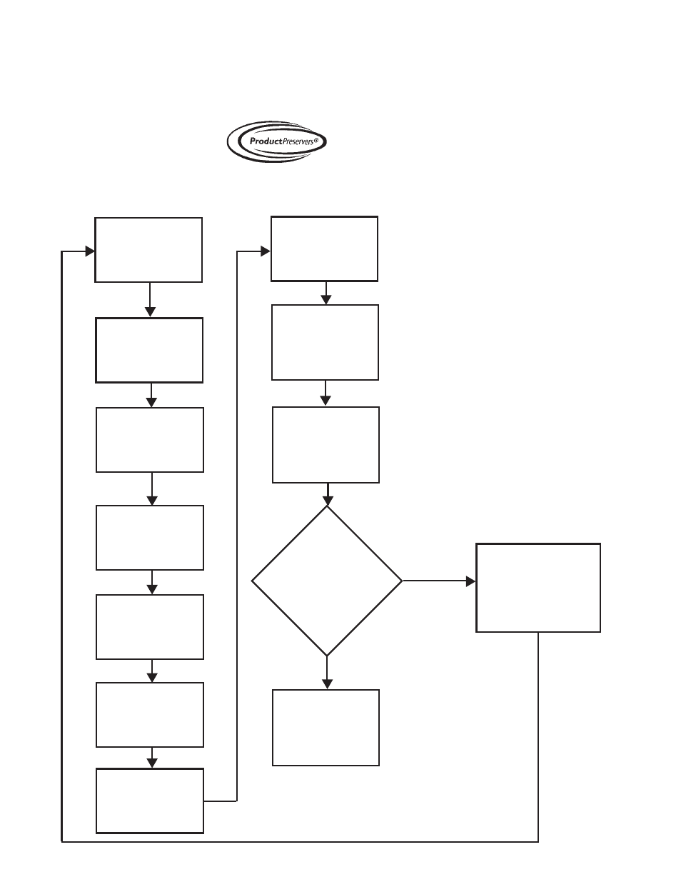
SEQUENCE OF OPERATION FLOW CHART
Description of this flow chart can be found in the “SEQUENCE OF OPERATION” section found on page 23.
Switch power on
to unit.
Thermostat calls
for heat.
Ignition Control
Board performs
diagnostic check on
components
Ignition Control
Board sends power
to Exhaust Inducer
Exhaust Inducer
engages Prover
Switch
Ignition Control
Board provides
power to Silcon
Nitride Ignitor
Silicon Nitride
Ignitor
warms up for
20 seconds
Ignition
Control Board
opens Gas
Valve.
Ignition Control
Board shuts off
Silicon Nitride
Ignitor after
3 seconds
Ignition Control
Board waits 3 more
seconds to
monitor Flame
Sensor.
Did Main
Burner Light?
YES
Ignition Control
Board monitors
units until T’Stat
is satisfied.
Ignition Control
Board shuts off Gas
Valve and allows the
Exhaust Inducer to
purge appliance for
20 seconds.
NO