Warning – Alliance Laundry Systems Clothes Dryer User Manual
Page 10
© Copyright, Alliance Laundry Systems LLC – DO NOT COPY or TRANSMIT
510963
10
4. Tighten all connections securely. Turn on gas and
check all pipe connections (internal & external)
for gas leaks with a non-corrosive leak detection
fluid.
NOTE: The dryer and its appliance main gas valve
must be disconnected from the gas supply piping
system during any pressure testing of that system
at test pressures in excess of 1/2 psi (3.45 kPa).
Refer to Step 9 (Check Heat Source).
L.P. (Liquefied Petroleum) Gas, 2500 Btu/ft
3
(93.1 MJ/m
3
) service must be supplied at 10 ± 1.5 inch
water column pressure.
For proper operation at altitudes above 3000 feet (915 m)
the L.P. gas valve spud orifice size must be reduced to
ensure complete combustion. Refer to Table 3.
NOTE: DO NOT connect the dryer to L.P. Gas
Service without converting the gas valve. Install
L.P. Gas Conversion Kit 649P3, available at extra
cost.
Step 4: (Electric Dryer Only) Connect
Electrical Plug
Dryer requires 120/240 Volt or 120/208 Volt, 60 Hertz,
3 wire electrical suppy. Refer to serial plate for
specific electrical requirements.
IMPORTANT: Use only a new U.L. listed No. 10
(copper wire only) three conductor power supply
cord kit rated 240 Volts (minimum) 30 Amperes
and labeled as suitable for use in a clothes dryer.
NOTE: The wiring diagram is located inside the
control hood.
Grounding Information
• This dryer must be connected to a grounded
metal, permanent wiring system; or an
equipment-grounding conductor must be run
with the circuit conductors and connected to the
equipment-grounding terminal or lead on the
dryer.
• The dryer has its own terminal block that must be
connected to a separate branch, 60 Hertz, single
phase circuit, AC (alternating current) circuit,
fused at 30 Amperes (the circuit must be fused
on both sides of the line). Electrical service for
the dryer should be of maximum rated voltage
(208 or 240 Volt, depending on heating
element) listed on the nameplate. Do not
connect dryer to 110, 115, or 120 Volt circuit.
• Heating elements are available for field
installation in dryers which are to be connected to
electrical service of different voltage than that
listed on nameplate, such as 208 Volt.
NOTE: Branch circuit wire size requirements to
laundry room outlet are shown in Table 4.
• The power cord connection between wall
receptacle and dryer terminal block IS NOT
supplied with dryer. Type of power cord and
gauge of wire must conform to local codes.
L.P. Altitude Adjustments
Altitude
Orifice Size
Part No.
feet
m
No.
inches
mm
3000
915
55
0.0520
1.32
58755
8000
2440
56
0.0465
1.18
503786
Table 3
Wire Length
Dryer
Less than
4.5 m (15 ft.)
Listed No. 10 AWG
Copper wire only
Longer than
4.5 m (15 ft.)
Listed No. 8 AWG
Copper wire only
Table 4
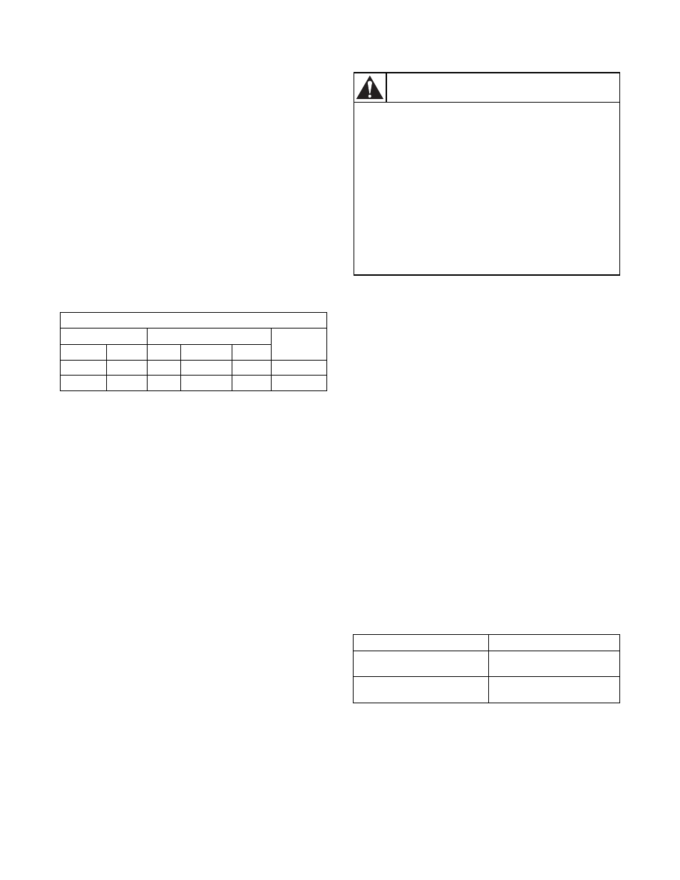
To reduce the risk of fire, electric shock,
serious injury or death, all wiring and
grounding MUST conform with the latest
edition of the National Electrical Code,
ANSI/NFPA 70, or the Canadian Electrical
Code, CSA C22.1, and such local
regulations as might apply. It is the
customer’s responsibility to have the wiring
and fuses installed by a qualified electrician
to make sure adequate electrical power is
available to the dryer.
W521
WARNING