Electrical, Important! read before installation, Installation and maintenance – Ultravation UMX EZUV Signature Series- DC-OH-0229 User Manual
Page 2
Ultravation.com
DC-OH-0229A
Installation and Maintenance
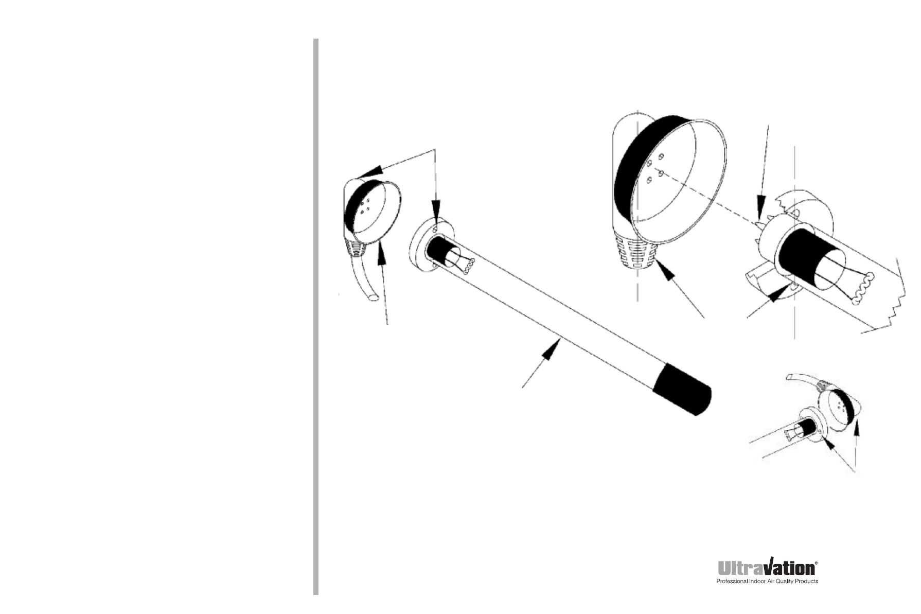
Lamp lead (rubber
sleeved female
receptacle)
Note that lamp connector pin pattern
is NOT square.
It can be mounted from either side
and top or bottom depending on the
orientation of the installed lamp.
Electrical
NOTICE: All 24 volt UV equipment for HVAC systems
(regardless of manufacturer) must be installed using
a separate, dedicated minimum 40VA transformer to
avoid the possibility of voiding UL certification of the
HVAC system.
The screw holes on the UV lamp
need to be parallel to the lamp lead
cord on the back of the female
receptacle for correct assembly!
Lamp screw holes and lamp lead
cord need to be parallel
UVC lamp
Horizontal orientation of
the lamp lead requires
installing the lamp with
screws left to right.
Installation steps for internal mounting of power supply:
1. Mount power supply inside of the air handler but out of the air stream as much as
possible. Place the power supply close to the control panel for ease of connecting to
24 VAC or appropriate voltage according to the power supply label.
2. To utilize the internal mounting bracket, first install the bracket inside the air handler
in a location that will position the UV lamp such that it bathes the entire surface to be
treated. Plug the lamp connector onto the lamp and snap into the bracket.
Note: The rectangular pin pattern can be mated in two positions only.
3. Connect power wires to a dedicated minimum 40VA transformer. This must be done in
accordance with all state and local electrical and building codes.
Maintenance
Never perform maintenance on the UV unit without disconnecting power. Typical
maintenance consists of replacement of the ultraviolet (UV) lamps. UV lamps undergo a
photochemical process during operation, that slowly reduces the amount of UV light
generated to disinfect the air and surfaces. For optimum air stream disinfection UV lamps
should be replaced annually. For surface disinfection, lamp replacement should be
performed no later than every two years (see below, “Important Information about UV
lamp replacements”). When installing new lamps, ensure that the lamp glass is free from
any fingerprints or debris, as this may alter the path of the UV energy. Use rubbing
alcohol and a dry cloth to remove any surface contamination.
Important information about UV lamp replacements
Replace UV lamp(s) annually in order to maintain optimum effectiveness in the reduction
of pathogens such as bacteria, viruses and microscopic mold. Lamps operating after a
period of 18,000 hours (two years) no longer provide adequate UV-C. When the UV lamp(s)
reach the end of the 18,000 hour useful operating life, the unit automatically turns off. The
UV lamp must be replaced and the power supply reset. Do not reset the power supply
without replacing the UV lamp as worn out UV lamps draw excessive electrical
current which may result in damage to the UV system, and may void the warranty.
Important! Read before installation
We recommend that this unit be installed and maintained by a trained HVAC
professional technician.
Installation steps for external mounting of power supply:
1. Determine a suitable location to install unit housing. Mounting location should be of
sufficient strength as to support the unit, otherwise reinforcement of the ductwork may
be necessary. Fasten the unit in place with two self-tapping screws (supplied).
2. Select location for UV lamp module. Drill a 1" hole. Install mounting plate over
drilled hole with screws provided. Insert UV lamp into hole. Attach to mounting plate
system with two self-tapping screws (supplied).
3. Attached the rubber lamp connector fully onto the installed UV lamp assembly. Be
sure the four pinholes are orientated properly to the four matching pins on the lamp
(see diagram at right).
4. Connect power wires to a dedicated minimum 40VA transformer or hardwire to
appropriate voltage based on requirements listed on power supply label.
This should be done in accordance with all state and local electrical and
building codes.
Notes: The UV lamp assembly can be removed independently, by removing the
two screws in the lamp holder.
The rectangular pin pattern allows connection in two positions (see other
side of this sheet).
A UV status viewport lens is supplied to verify lamp operation. Drill a 3/8"
hole within a 3" radius around the lamp, and on the “lamp side” of the “V” in
the light shield. Snap viewport into place.