Ultravation UVPhotoMAX - DC-IH-0234 User Manual
Uv photo max, Homeowner / user guide, Professional indoor air quality product
2
Thank you for purchasing an Ultravation
®
Professional Indoor Air Quality Product
•
Steel electrical housing
•
Mounting plate / PCO module
•
4- 3/4 inch 5/16 self tapping
sheet metal screws
•
UVC warning label
•
Warranty card
•
Remote mount viewport label
•
Remote mount viewport / sight
stick
•
One 12" photocatalyst oxidation
Dual Spectrum UV lamp
•
Sealing Gasket
•
Two wire nuts
•
40 VAC multi-tap transformer
Package Contents:
Introduction
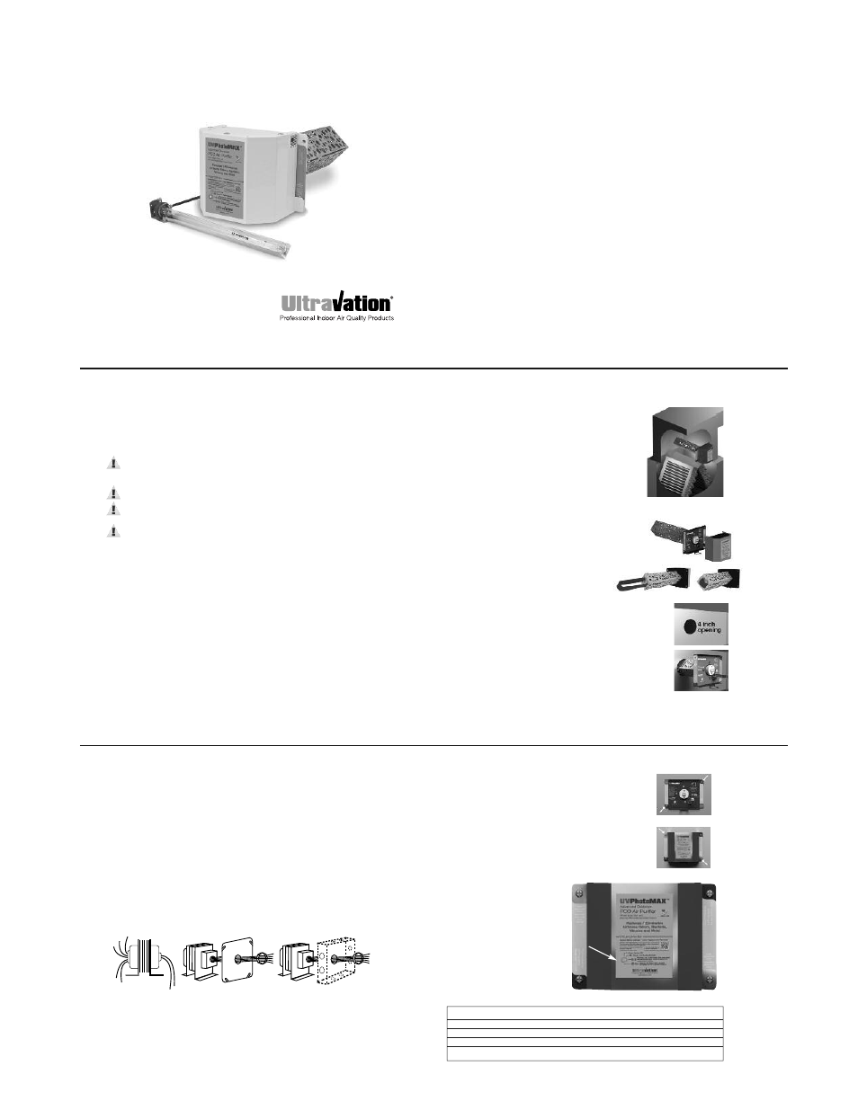
The Ultravation
®
UVPhotoMAX
™
for HVAC is a unique air quality improvement
device that uses a photocatalytic (PCO) process to treat the air for organics
from microorganisms to allergens to odors.
The UVPhotoMAX will be effective when used in structures up to 5,000 sq. ft.
Homeowner / User Guide
UV
Photo
MAX
ª
1-866-GO-UV-AIR (468-8247)
ultravation.com
DC-OH-0234M R1013
Advanced Oxidation Photocatalytic
Whole House Air Purifier
For HVAC systems
PTX-1200F
(shown with EZ-Light™ option)
4
1. Determine a location for the UVPhotoMAX.
Mount the unit on the exit
or supply side of the HVAC system and
before the ductwork branches off.
2. Separate the power module from the
mounting plate. See Fig. 1.
3.
Remove blue lamp protector. See Fig. 2.
4. Mark a 4" round opening (or use the
end of the PCO chamber to mark the
area) on the air duct and cut the hole
needed for the insertion of the
advanced photocatalytic chamber.
See Fig. 3.
5.
Thread supplied gasket over PCO module
and attach to mounting plate. (Seals against
air duct.)
6. Insert the mounting plate / PCO module into
opening and attach to duct with two supplied self
tapping screws in the lower left and upper right
(only). See Figs. 4 and 5.
Typical placement in
HVAC system
Fig. 3
Fig. 1
Installing the UVPhotoMAX
™
Fig. 2
Fig. 4
3
SAFETY PRECAUTIONS:
It is recommended that this unit be installed and maintained by a trained
technician:
WARNING: UV Hazard. Always protect eyes from ultraviolet light.
NEVER look at UV lamps in operation. Unplug or disconnect power
before replacing lamps or servicing.
WARNING: Severe eye damage or temporary blinding may occur.
WARNING: DO NOT operate outside of air handler. Operate only
after installed.
WARNING: No openings in HVAC system are allowed which would
give direct line-of-sight to the UV light.
In the event of accidental breakage or replacement of the ultraviolet lamp,
please ensure that the lamp is disposed of in accordance with local and state
environmental laws regarding fluorescent lamps containing mercury.
Notice: All wiring inside air handling system in direct line of site of the UV
lamp must be shielded with aluminum foil tape or equivalent non-combustible
material. When installing this unit, select a mounting location that prevents
ultraviolet light exposure to plastic non UV-rated flexible duct liner or
other plastic components with unknown resistance to ultraviolet light.
Ultraviolet light may cause color shift or structural degradation of plastic
HVAC components. If installing where UV light can directly contact fiberglass
duct board, contact manufacturer of fiberglass product for advice on UV
rating. If unknown, install metal sheathing or foil tape to completely protect
fiberglass duct board from UV light exposure.
7.
Adjust Photon Clarifier. See page 7.
8. Place the power module on the unit aligning holes
in tabs with holes in mounting plate (upper left /
lower right). See Fig. 6.
9. Secure the power module to the mounting plate with
the remaining two self-tapping screws.
10. Plug power cable in.
5
Fig. 5
Fig. 6
LED
Audible Alarm
Unit Status
Green
No Sound
Normal
Flashing red
3 Min beep
One year use exceeded
Pulsing red
1 sec beep
Lamp out, service required
Steady Red
No Sound
Replace lamp(s)
UVLampMonitor Status
Your UVPhotoMAX is equipped
with an electronic power supply
that monitors operation and
protects the UV lamp filaments.
It also monitors elapsed time and
reminds after 9000 hours of
operation that lamps need to be
replaced. Below is a chart that
describes how to interpret
the display.
6
24VAC Transformer
1.
Disconnect power supply before beginning installation to prevent
electrical shock or equipment damage.
2. Connect secondary voltage. Refer to voltage color or terminal coding on
transformer for proper wire combination. On terminal type transformer, be
sure that no exposed wire can come in contact with any terminal.
3. Connect primary voltage. Refer to voltage color coding on transformer for
proper wire combination. See Fig. 1 for connection and installation.
4. Tape or protect all unused exposed wire separately to avoid a possible
electrical short.
5. Check installation and reconnect power supply for proper operation.
Common
120
208
240
277
VAC
24 VAC
Fig. 1 Connect power to proper line voltage
Fuse
Some models are equipped with an in-line fuse. If necessary, replace with an
AGC type fuse, 2 AMP MAXIMUM.