Ultravation UVPhotoMAX - DC-IH-0234 User Manual
Page 2
8
Model
Description
Replacement Part Number
PCO Lamp
12" Dual Spectrum Lamp
AS-IH-1013
PCO Module
Replacement base
94-201
EZ-Light
12" UVC Lamp
AS-IH-1001
EZ-Light
17" UVC Lamp
AS-IH-1003
Replacement Parts
Maintenance
Typical maintenance of the UVPhotoMAX™ system includes recommended
annual service and the replacement of the Dual Spectrum UV Lamp. UV
lamps undergo a photochemical process during operation that slowly
reduces the amount of germicidal UV light generated.
When installing new lamps, ensure that the lamp glass is free from any
fingerprints or debris, as this may alter the path of the UV energy. Use
rubbing alcohol and a dry cloth to remove any surface contaminants.
7
Adjusting the Photon Clarifier
The UVPhotoMAX™ is a universal air
purifier with a patented design that provides
adjustability to the advanced photocatalytic
process for a variety of treated space sizes.
When setting up your equipment, adjust the
Photon Clarifier Adjuster (under electronics
cover) to the appropriate position based on
the square footage of the home or CFM of
the air handler.
Fine adjustments may be required
depending upon household living characteristics.
For more information please call Ultravation Customer support at
1-866-468-8247.
500
1000
2000
2500
3000
3500
4000
4500
5000
10000
6000
7000
8000
9000
2000
4000
5000
3000
1000
CFM
Sq. Ft.
Photon Clarifier
Adjustment
Service Indicator Reset
1. To set or reset the Bi-Annual Service Indicator the unit
must be connected and have power.
2. Press and hold the square yellow RESET button for 10
seconds using a non-metallic implement. The LED should
turn blue while the button is depressed.
3. Release the RESET button, and the LED will return to
green status.
10
EZ-Light™ UV Option
A UVPhotoMAX™ is capable of powering an optional single Ultravation
®
T3™
Germicidal UV lamp to keep HVAC internal surfaces clear of mold which re-
duces airborne mold allergen and helps minimize HVAC energy consumption.
The EZ-Light™ option may be advisable in the southern regions or where
there is a constant demand for air conditioning. Heavier use frequently leads
to bacterial/mold fouling of AC equipment. In these cases it may be beneficial
to add a 3rd lamp for items such as blower motor assemblies or turning vanes.
Stand-alone Ultravation
®
UltraMAX™ Germicidal UV light kits are available.
We recommend that this unit be installed and maintained by a trained HVAC
professional technician. Consult your HVAC service provider or call 1-866-468-8247
for more information.
Installation Steps (If EZ-Light was purchased separately see instruction
for connection to UVPhotoMAX accompanying EZ-Light.)
1.
Select location for UV lamp. Drill a 1" hole. Install mounting plate over
drilled hole with the provided screws. Insert UV lamp module into hole.
Attach to HVAC system with two provided self-tapping screws.
2.
Plug the rubber lamp connector fully onto the installed UV lamp assembly.
Be sure the four pinholes are oriented to match the four pins on the lamp
(see diagram pg. 11).
Notes:
The rectangular pin pattern allows connection in two positions (see diagram pg. 11).
A UV status viewport lens is supplied to verify lamp operation. Drill a 3/8" hole within a 3"
radius around the lamp, and on the “lamp side” of the “V” in the light shield (if used), to
accommodate installation of the viewport.
9
Lamp Replacement
The UV lamp is shipped installed in the equipment and should be replaced
during an annual service. To replace the UV Lamp follow the steps below:
Important Information About UV Lamp Replacements
Replace UV lamps at each annual service in order to maintain optimum
effectiveness in the reduction of pathogens such as bacteria, viruses and
microscopic mold. Lamps operating beyond one year do not provide
adequate reduction of pathogens and must be replaced. Lamps operating
beyond two years draw excessive electrical current which may result in
damage to the UV system. If UV lamp(s) have been operating for more than
two years, the system must be turned off until replacement lamp(s) are
installed. Failure to do so may void the warranty.
1. Unplug power cord
and remove power
module. See Fig. 1.
2. Note the position of
the Photon Clarifier
and pull adjustment
bar to its full-out
position. See Fig. 2.
3. Remove lamp screws
and pull lamp out of
PCO module.
See Fig. 3.
4. Install new lamp and
fasten with lamp
screws.
5. Return the Photon
Clarifier to its noted
setting.
6.
Place the power
module on the unit
and fasten.
7.
Plug in power cord.
Fig. 1
Fig. 2
Fig. 3
Warranty
Ultravation
®
UVPhotoMAX™ features a ten-year warranty, with the exception
of the ultraviolet lamp(s), which are warranted for a period of one year after
date of consumer purchase.
This warranty does not include damage to the unit from accident, misuse or
improper installation.
If this product should become defective, Ultravation will elect to repair or
replace the product free of charge. Ultravation will return repaired or replaced
warranted products pre-paid to the customer, provided that the product was
delivered pre-paid.
Ultravation shall have no responsibilities for charges incurred by the
customer for installation or removal of warranted items. Liability is limited
only to the replacement or repair of this product.
This warranty gives you specific legal rights, and you may also have other
rights, which vary from state to state. All returns must be accompanied by a
return authorization number, which may be obtained by contacting
Ultravation, Inc.
Ultravation, Inc.
Phone: 1-866-GO-UV-AIR (468-8247)
www.ultravation.com • [email protected]
Ultravation.com
UL Listed. The health aspects associated with the use of this
product and its ability to aid in disinfection of environmental
air have not been investigated by UL.
5TA2
Ultravation’s T3™ system is protected by US patents 6,809,326B2 and 6,838,057B2 • Copyright © Ultravation, Inc. All rights reserved.
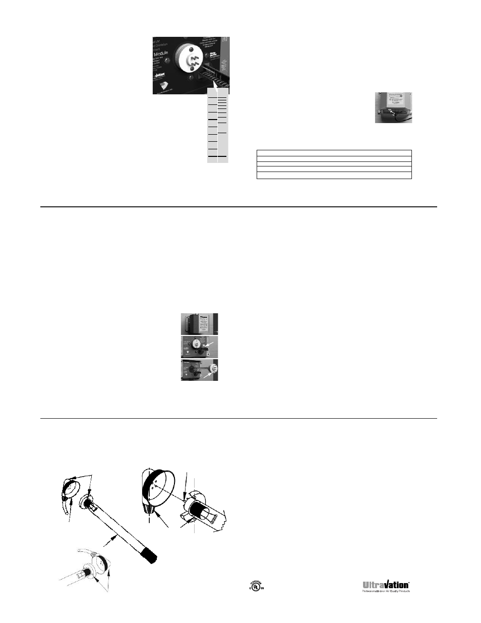
11
The screw holes on the UV lamp must
to be parallel to the lamp lead cord on
the back of the female receptacle for
correct assembly!
Lamp Lead
(rubber sleeved
female receptacle)
Lamp screw
holes and lamp lead
cord need to be parallel
Horizontal orientation of the lamp
lead requires installing the lamp
with screws left to right.
Note that lamp pin pattern is NOT square.
It can be mounted from either side and top
or bottom depending on the orientation of
the installed lamp.
EZ-Light UV Option Diagram
UVC Lamp