UEi Test Instruments DM5B User Manual
Page 4
To measure current, you must break the circuit under test (cut a wire
for example) and make the meter part of the circuit. This creates two
connection points. On one side is the power source and the other is the
load. If DC current is being measured, a minus sign will be displayed
when current is flowing opposite to the connection polarity.
1. Ensure power is off to the circuit to be tested.
2. Set the rotary switch to the mA or 5A position (depending on the
maximum possible amperage you will be measuring). The meter
will default to the DC current setting. If you have an AC current
source, press the “DC/AC” push-button to switch to AC. Th meter
i n d i cates which mode you have selected at the far left of the display.
3. Create a break in the circuit as described earlier and connect the
meter leads to the two points created at the break.
4. Apply power to the circuit and note your measurement value.
WARNING!
Do not remove the leads from the circuit until power is disconnected.
M a i n t e n a n c e
Periodic Service
WARNING!
Repair and service of this instrument is to be performed by qualified
personnel only. Improper repair or service could result in physical
degradation of the meter. This could alter the protection from
electrical shock and personal injury this meter provides to the
operator. Perform only those maintenance tasks that you are
qualified to do.
These guidelines will help you attain long and reliable service from
your meter:
• Calibrate your meter annually to ensure it meets original
performance specifications
• Keep your meter dry. If it gets wet, wipe dry immediately -
Liquids can degrade electronic circuits
• Whenever practical, keep the meter away from dust and dirt
that can cause premature wear
• Although your meter is built to withstand the rigors of daily use,
it can be damaged by severe impactsUse reasonable caution
when using and storing the meter
Cleaning
Periodically clean your meter’s case using a damp cloth. DO NOT use
abrasive, flammable liquids, cleaning solvents, or strong detergents as
they may damage the finish, impair safety, or affect the reliability of the
structural components.
Clean the input terminals as follows:
1. Turn the meter off and remove all test leads.
2. Shake out any dirt that may be in the terminals.
3. Soak a new swab with alcohol and work the swab around in
each terminal.
Battery and Fuse Replacement
When the battery icon appears in the upper right of the display, the
batteries must be replaced immediately. Low battery voltage can cause
incorrect readings and consequential damage.
1. To replace the batteries, remove the meter from its ca r rying ca s e .
2. Slide the battery cover plate (on the back of meter) out.
3. Replace both batteries at once with type listed in the specifica t i o n s .
4. Reassemble the meter.
Fuse Replacement
WARNING!
Replace fuses with the type listed in the specifications (also printed on
the circuit board) only.
1. To replace the fuses, remove the meter from its ca r rying ca s e .
2. Slide the battery cover plate out (on the back of meter).
3. Remove the three back panel retaining screws and separate the
two halves.
4. Locate and replace expended fuse.
• 5A near the bottom
• .5A near the middle
5. Reassemble the meter.
S p e c i f i c a t i o n s
NOTE: Accuracy is stated as ± (% of reading + number of least
significant digits) at 32 to 104˚F, with relative humidity up to 80%.
Stated accuracy is valid for a period of one year after calibration. AC
conversions of this meter are average responding and calibrated to
the RMS value of a pure sine wave input.
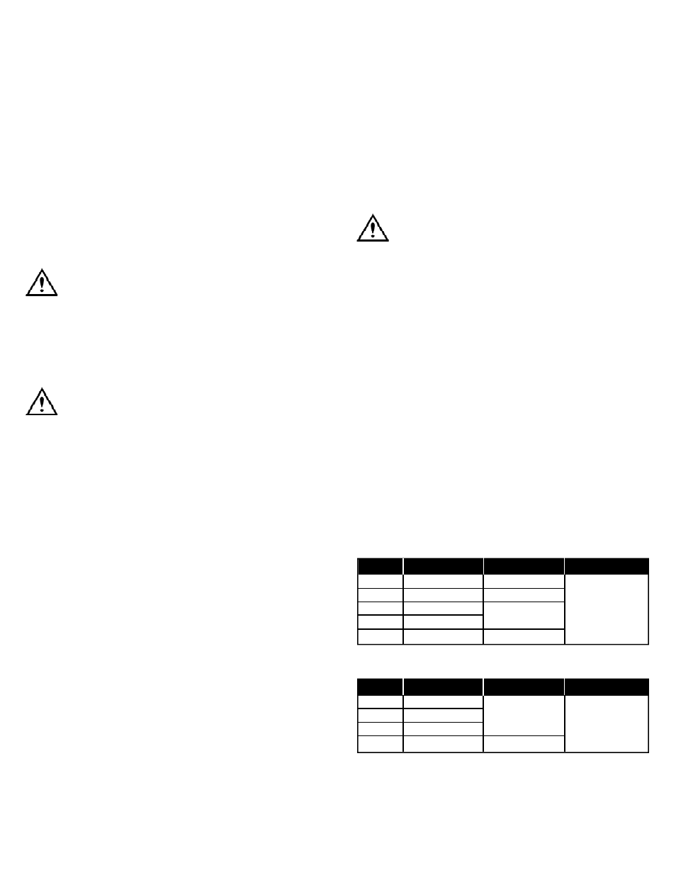
DC Voltage
AC Voltage
DM5B-MAN
P. 3
Range
Resolution
Accuracy
Protections
300 mV
0.1 mV
±(1.2% + 2 digits)
3 V
.001 V
±(0.5% + 2 digits)
30 V
.01 V
±(1.2% + 2 digits)
1000 V
300 V
.1 V
750 V
1 V
±(1.5% + 3 digits)
Range
Resolution
Accuracy
Protections
3 V
.001 V
30 V
.01 V
±(2.0% + 3 digits)
300 V
.1 V
1000 V
750 V
1 V
±(2.0% + 4 digits)