UEi Test Instruments C50OILKIT User Manual
Page 4
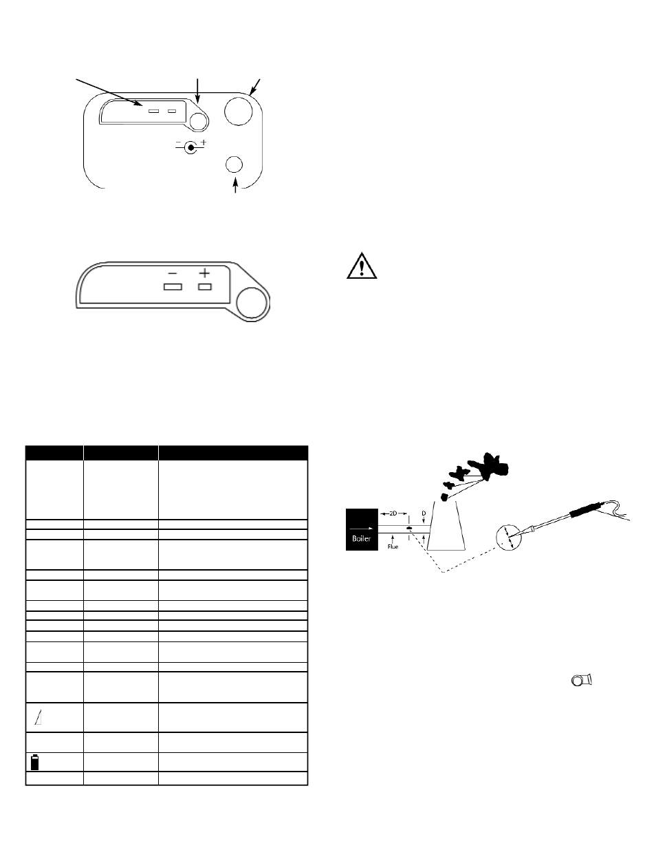
Analyzer Connections
NOTE: Take care when inserting the temperature probes as the pins are
polarized. Insert with the smaller pin (+) to the right. A view of the
sockets is shown below.
Automatic Calibration
During this sequence the analyzer pumps fresh air into the Oxygen and
CO (C75 only) sensors to allow them to be set to 20.9% and zero
respectively. See “Setting Inlet Temperature) for information on options.
Changing the Display
The parameters on the first line display are selected from the following
using the pump key (press and hold for display item to change). Certain
items are available on the lower display by selecting with the rotary dial.
*Available on the second line of the display.
C50/C75-MAN
P. 3
Setting Inlet Temperature
During the automatic calibration sequence the burner INLET (Ti)
temperature used in the NET temperature calculation is stored in the
analyzer. There are two methods of storing the INLET temperature.
A. Without the flue probe connected temperature inside the analyzer
is used (ambient temperature).
B. If the flue probe is connected the temperature of the probe tip is
used. This can be useful when the temperature of the air entering
the burner is different than the ambient temperature of the room.
NOTE: On ducted inlets, insert the probe tip into the inlet air during the
zero countdown. The analyzer will then store this temperature as the
ambient (inlet) for use in efficiency calculations. Do not sample flue gas
during the zero countdown.
WARNING!
If the INLET temperature is set incorrectly, then errors will be made in
the calculation of net temperature and efficiently.
Sampling the Flue Gas
Once the automatic calibration procedure has been completed and the
specific fuel has been selected (see menu options) the probe can be
inserted into the desired sampling point.
It is recommended that the sampling point be located at least two flue
diameters downstream of any bend, as close to the source as possible,
and that the probe tip is in the center of the flue. With balanced flues
and other domestic units the probe should be positioned far enough
into the flue so that no air can “back flush” into the probe.
The probe depth stop cone provided with the instrument allows the
probe to be used in holes whose diameters range from 1/4 to 4/5 inch
(6 mm to 21 mm).
The standard probe is rated at 1112˚F (600˚C).
TIP: To conserve battery power, switch off the pump when you are not
taking a measurement. To turn pump ON or OFF press “ “.
View data and rotate the dial to see flue changes as you make
adjustments. Press “HOLD” first to freeze or store the readings
before printing.
Display
Item
Note
NAT GAS*
Fuel selected
Fuel indicator
• NAT Gas
Natural Gas
• Propane
• Butane
• L Oil
Light Oil
• LPG
Liquid Petroleum Gas
R 0.0000
CO/CO2 ratio
Measured CO divided by calculated CO2
P 0.00
Poison index
CO/CO2 ratio x 100
AMB xx
Ambient temperature
Either instrument internal temperature or
(used as inlet
stored inlet temperature set during zero
temperature for ∆T)
countdown
COa
CO air free reading
CO reading adjusted to 0% O2 (C75 only)
O2
O2 Ref
O2% reference value to calculate readings
normalized to a set O2 level.
hh:mm:ss*
Time
Currently set time
MM/DD/YY*
Date
Currently set date
CO2*
Carbon Dioxide
Calculated CO2 value
O2*
Oxygen
Measured O2 value
∆T*
T Nett
Difference between Flue Temp and Ambient
(or inlet temperature)
TF*
T Flue
Measured Flue Temperature
η (G, N or C)*
Efficiency
Displays calculated efficiency when O
2
values are less than 18%. Displayed as
ηN, ηG or ηC as selected by the user.
Losses (C50 only)
Losses calculated from Oxygen and type of
fuel. Displays reading during a combustion
test. “----” is displayed while in fresh air.
CO*
Carbon Monoxide
Displays Carbon monoxide values in PPM as
(C75 only)
CO. Display value in mg/m
3
as COm.
*
Battery level
λ*
Excess Air
Flue (Tf) temperature
socket
Mains adapter socket
Flue gas inlet
Water trap drain plug