Introduction, 2 installation, 1 product range covered – Timeguard TPSL04 User Manual
Page 5
Complies with
EN60669
IP55
weatherproof
rating
Tough, durable
impact resistant
housing
Bottom cable entry with
cut to size grommet
5 x 20mm
cable entries
Cut to size
blind grommet
2 x drain hole cut
outs (if required)
2 x Earth
terminals
2 x 8 fixing
holes
5 x 20mm
conduit
knockouts
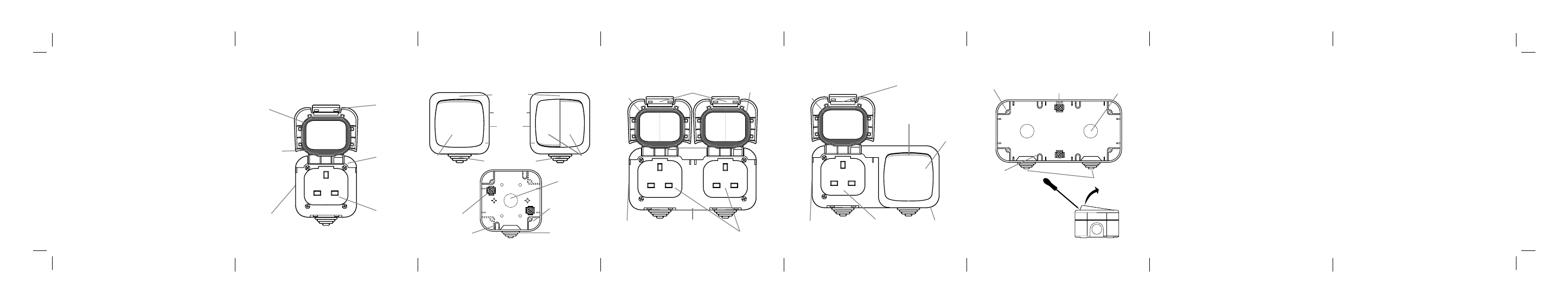
1 Product Range Covered
TPS101
Single Socket Outlet Unit
Single Gang
Back Box
(TPS101, TPSL01,
TPSL02, TPSL03,
TPSL04)
Easy lift
spring back
lid cover
Suitable
for all BS
13 amp
plugs
5 x 20mm
knockout
cable entries
Special IP55
weatherproof
seal
IP55
weatherproof
rating
Tough,
durable
impact
resistant
housing
Introduction
PowerSeal products (shown here) are a
cost effective range of switches and socket
outlets designed for external use with the
necessary IP (water and dust protection)
rating established by an independent test
authority.
The socket outlets cannot be used while it is
raining since there is no protection while a
plug is in the socket but users would not be
operating most commonly available DIY and
gardening equipment in the rain.
The tough, impact resistant casings of this
range give good physical protection in
outdoor locations.
Water may accumulate outside the sealed
area. To ensure full safety wipe the face of
the socket before use.
TPS201
Double Socket Outlet Double Gang Unit
TP203
20A Switch and 13A Socket Outlet Double Gang Unit
Double Gang Back Box
(TPS201, TP203)
Easy lift spring
back lid covers
Easy lift spring
back lid cover
Suitable for
all BS 13 amp
plugs
Suitable for
all BS 13 amp
plugs
Tough, durable
impact resistant
housing
Tough, durable
impact resistant
housing
8 x 20mm
knockout
cable entries
8 x 20mm
knockout
cable entries
Special IP55
weatherproof
seal
Special IP55
weatherproof seal
IP55 weatherproof
rating
IP55 weatherproof
rating
Rocker
Cut to size
blind grommets
4 x drain hole cut
outs (if required)
Switch rocker should be
removed by prising off with
a flat screwdriver. Use a
piece of card to prevent
marking the the unit.
4 fixing holes
8 x 20mm conduit
knockouts
2 x Earth
terminals
2 Installation
This product must be installed in accordance with the appropriate
Building and Wiring Regulations.
In all cases if there is a doubt as to how to proceed with an
installation consult a qualified electrician, your Local Authority’s
Building Control Department or the Timeguard Helpline
(020 8450 0515).
For the switches the screws holding the case halves together are
located beneath the rocker(s) (front plate switch actuator(s)).
To remove the rocker first press rocker inwards at the blind grommet
end, then, removing hand from there, force fingers as far as possible
between the opposite end of the rocker and the case, pulling the
rocker outwards. The rocker will unclick at it’s pivot point.
If it is not possible to exert enough force by hand, use the
technique shown at the foot of the previous page.
2.1 Cable Entry
Try to avoid siting the units in areas where there is direct sunlight for
any length of time.
Cable entry can be made via conduit into any of the 5 (8 for the
double socket TPS201 and switch socket TP203) knock outs on the
top, bottom, sides or back of the back box. In all cases ensure there
is a drain hole at the lowest point in the attached conduit system.
The knock out outline should be heavily scored with a sharp knife
before tapping out.
The appropriate sealing washers for the conduit in use must be
used to maintain the IP rating. The use of any knock outs apart
from the one(s) at the bottom requires that the lower drain hole(s)
on the back box is opened and the IP rating may well be reduced.
The blind grommets may be used for cable entry at the bottom
20mm hole(s). They must not be used in any other position
(including the rear) or the IP rating may be severely prejudiced.
The blind grommets should be pierced centrally to give an
undersize hole of a similar shape to the cable cross section.
2.2 Fixing Back Box
Drill 2 holes (4 for the double socket TPS201 and switch and socket
TP203) according to the dimensions given on the rear of the back
box. Fix with round head no. 8 woodscrews or equivalent using
wall plugs if necessary. The length of the screw will depend on the
surface being fixed to, for example fixing to roughcast would
require a longer screw than fixing to brickwork.
2.3 Connecting Cables
Allow sufficient excess cable to wire up the socket(s) or switches
but not too much to make it difficult to close the front plate onto
the back box.
TPSL02
Double Switch
(single gang size)
TPSL01
Single Switch
TPSL03
Single Bell
Push Switch
TPSL04
20AX DP Switch
Rocker
Rockers