Commercial gas tankless water heaters – Takagi T-M32 User Manual
Page 2
Commercial Gas
Tankless Water Heaters
Page 2 of 2
www.takagi.com
TCGSS00313
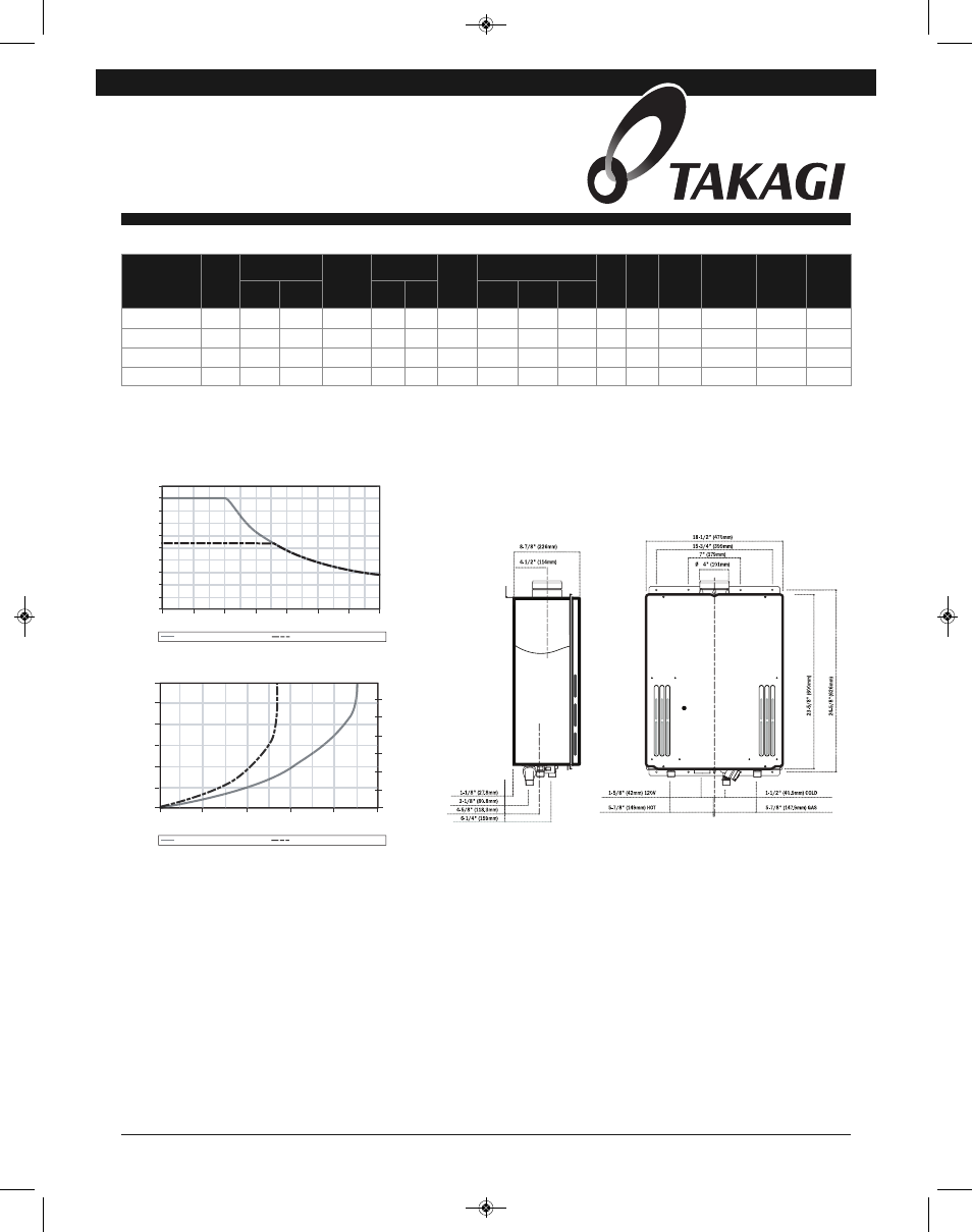
All dimension in inches.
15-150 psi water pressure. 40 psi or above recommended for maximum flow.
*Current numbers based on factory testing, 0.5 GPM required for activation, 0.4 GPM required for continuous fire after initial ignition.
**Category III required
Pressure only relief valve required (Min. 240,000 BTUs. 150 PSI).
MODEL
NUMBER
FUEL
TYPE
GAS CONSUMPTION
INPUT
THERMAL
EFFICIENCY
INLET GAS
PRESSURE
MAX
GPM*
DIMENSIONS IN INCHES
VOLT
AMP
FLUE**
INTAKE
(OPTIONAL)
HOT/COLD
GAS
CONN.
APPROX.
SHIPPING
WEIGHT
(LBS)
MIN.
BTU/H
MAX.
BTU/H
MIN.
in. w.c.
MAX.
in. w.c.
HEIGHT
WIDTH
DEPTH
T-M32-N
Natural
24,000 240,000
82%
5.0
10.5
0.5-9.0
23-5/8
18-1/2
10
120
0.94
4” O.D.
4” O.D.
3/4” NPT
66
T-M32-P
Propane 24,000 240,000
82%
8.0
14.0
0.5-9.0
23-5/8
18-1/2
10
120
0.94
4” O.D.
4” O.D.
3/4” NPT
66
T-M32-N ASME
Natural
24,000 240,000
82%
5.0
10.5
0.5-9.0
23-5/8
18-1/2
10
120
0.94
4” O.D.
4” O.D.
3/4” NPT
66
T-M32-P ASME
Propane 24,000 240,000
82%
8.0
14.0
0.5-9.0
23-5/8
18-1/2
10
120
0.94
4” O.D.
4” O.D.
3/4” NPT
66
CLEARANCES:
INDOOR: Top 12”, Bottom 12”, Front 24”, Back 1”, Sides 2”
OUTDOOR: Top 36”, Bottom 12”, Front 24”, Back 1”, Sides 2”
Specification
The fully modulating, on-demand, gas fired tankless water heater(s) shall be Takagi Tankless Water Heater model T-M32 or T-M32 ASME, having a maximum input rating of 240,000 Btu/h and
available in NG or LP. The heater shall have ¾ in. male NPT water and gas connections. The inlet gas supply pressures shall be 5.0 in. WC (min.) up to 10.5 in. WC (max) for NG and 8.0 in.
WC (min.) up to 14 in. WC (max.) for LP. The heater(s) can use an accessory temperature remote, TM-RE30/9007603005, that can be installed up to 400 ft. from the heater using 18 gauge
(minimum) control wire. The temperature remote shall provide diagnostic information, fault history, and heater set temperature. The heater(s) shall operate using 120 V / 60 Hz power source.
The heater(s) shall be vented with 4” diameter Category III vent pipe with a length not to exceed 50 ft. (equivalent), terminating horizontally or vertically. The heater(s) can be direct vented
with optional direct vent conversion kit, TM-DV32/9007668005, using 4” diameter pipe. The intake pipe may use material such as PVC, ABS, aluminum, or Category III pipe and cannot exceed
50 ft. (equivalent) length. The outdoor installation shall use a vent cap, TM-VC32/9007676005.
The water heater(s) shall use a copper, fin tube heat exchanger with quick release brass or bronze waterways. The heater(s) shall be controlled by an onboard solid-state printed circuit board
which uses the following factory installed components: thermistors to monitor water temperature; a flow sensor to measure flow rate; a flame sensor to monitor combustion; an Air-Fuel Ratio
Rod to measure and adjust air input in order to maintain optimal combustion efficiency. The heater also consists of inline fusing and surge absorbers for electrical surge protection, an
electronic spark igniter, aluminized stainless steel burners, a hi-limit temperature switch, modulating gas valve, freeze protection that will use heating blocks to protect the heat exchanger,
and an overheat cutoff fuse.
The heater(s) can manifold to Easy-Link up to 4 heaters to provide additional capacity. The Easy-Link controls shall be built onto the onboard solid-state printed circuit board and does not
require external controls. The linking control wire shall be supplied with the heater. The heater(s) can use a Multi-Unit controller, TM-MC01/9007675005, to manifold 5-20 heaters. The Easy-
Link and Multi-Unit Controller shall modulate the system for the most efficient performance. The Easy-Link and Multi-Unit Controller shall rotate the priority heater every 12 hours of operation
time or 100 starts for balanced duty/cycle operation.
The heater(s) shall be CSA approved for sale in the United States and Canada, have a minimum thermal efficiency of 82%, meets ASHRAE 90.1-2007, complies with Low NOx emissions of
40 ng/J or 55 ppm, and shall be certified to NSF 5 Standards. The T-M32 ASME shall be certified by ASME with the HLW stamp.
10.0
9.0
8.0
7.0
6.0
5.0
4.0
3.0
2.0
1.0
0.0
0
20
40
60
80
100
120
140
Flow Rate Vs. Temperature Rise
Flow Rate (gpm)
Temperature Rise (°F)
10.0
8.0
6.0
4.0
2.0
0.0
0
20
40
60
15
30
25
0
10
10
20
30
50
Flow Rate (gpm)
Pressure Loss (psi)
Above shown rate is based on single unit only
Pressure Drop
5
Set temperature of 145° or lower Set temperature of 150° or higher
Set temperature of 145° or Lower Set temperature of 150° or higher
Head
(ft)
TCGSS00313 T-M32 Spec Sheet_Spec Sheet Template 12/19/13 4:22 PM Page 2