Float switch, Class 9037 type hg series a – Sterlco 4300 Series Stainless Steel Condensate Pumps User Manual
Page 7
Page 7 of 10
9037-891
9037-891
SERVICE
SERVICE
BULLETIN
BULLETIN
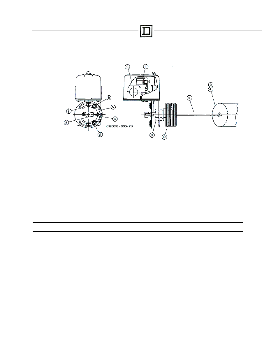
Class 9037 Type HG Series A
FLOAT SWITCH
CAUTION: Switches are shipped with a bracket attached to the mounting plate. This bracket prevents the float and rod from moving in the tank
during shipment. When installing the system, this clearly marked shipping bracket must be removed and discarded.
APPLICATIONS: For automatically controlling the liquid level in a closed tank by float movement.
MOUNTING: The Type HG Screw-in Tank Float Switches are mounted directly to the tank by means of the 2 ½” I.P.S. threaded fitting (D).
Before screwing this fitting into the tank, loosen Nut (C) so that the fitting (D) is free to rotate in the switch bracket. Tighten the fitting (D) so that
there will be no leak past the threads. Then revolve the switch case until it is horizontal and tighten Nut (C).
ENCLOSURE RATING: NEMA 1 ENCLOSURES ARE INTENDED FOR INDOOR USE PRIMARILY TO PROVIDE A DEGREE OF
PROTECTION AGAINST CONTACT WITH THE ENCLOSED EQUIPMENT IN LOCATIONS WHERE UNUSUAL SERVICE CONDITIONS DO
NOT EXIST.
WARNING: TO AVOID SHOCK HAZARD, DISCONNECT ALL POWER BEFORE INSTALLING OR SERVICING DEVICE.
ADJUSTMENTS: Switches are shipped from the factory set for a specified float travel. Resasonable adjustment of float travel can be made in
the field by moving adjusting strips (7) which are held in place by Screws (A) and (B). Loosening Screw (B) and moving upper adjustment strip (7)
will affect the upper limit of float travel only. Loosening Screw (A) and moving lower adjusting strip (7) will affect the lower limit of float travel.
REPLACEMENT PARTS LIST
Item
Number
Description
Number
Req’d.
Part
Number
1
Set of Moveable and Stationary Contacts …………………………………………….
2
9998 PC-242
2
Switch Mechanism
ℵ …………………………………………………………………….
1
65079-502-51
3
Float (304 SS) ……………………………………………………………………………
1
9049 HF3
4
Float (316 SS) ……………………………………………………………………………
1
9049 HF4
5
Adjusting Plate Assembly ………………………………………………………………
1
2810-D7-G1
6 Operating
Lever
…………………………………………………………………………. 1 65079-042-01
7
Adjusting Strip ……………………………………………………………………………
2
2810-X8
8
Set Screw ………………………………………………………………………………...
1
21801-14080
9
45° ……………...
-
……………..Connector and Rod Assy…….……….
1
2810-C3-G9
9
90° Offset ……...
3”
……………..Connector and Rod Assy……………..
1
2810-C3-G15
9
90° Offset ……...
4-1/4”
……………..Connector and Rod Assy……………..
1
2810-C3-G19
9
90° Offset ……...
5”
……………..Connector and Rod Assy……………..
1
2810-C3-G18
9
90° Offset ……...
7”
……………..Connector and Rod Assy …………….
1
2810-C3-G6
-
Seal and Installation Kit (BUNA-N) ……………………………………………………
1
9998 PC-337
-
Seal and Installation Kit (VITON) ………………………………………………………
1
9998 PC-338
ℵ Orders for mechanisms must show Class and Type so nameplate on replacement can be correctly stamped.