Installation – ProMariner ProIsoCharge User Manual
Page 6
10
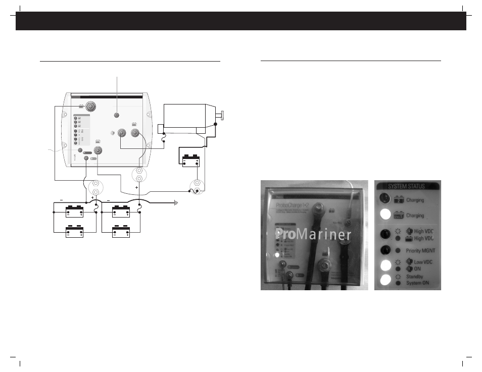
Guarding
The connections that are made to this unit are
high amperage. Ensure the protective rubber boots
are properly installed, followed by the provided
protective cover.
Note: Rubber boots are removed for clarity.
Start Up
Upon startup, the condition of the
LED indicators should resemble
this photo. The Engine battery has
been given priority, the alternator
is charging and the system is on.
Installation
Fuses/over current protection
General - The fuses can be up to 150% of the maximum output of the alternator. Each
conductor must be fused with the exception of the starting circuit, which is not required
to be fused.
Alternator – If the alternator is self-regulating and the conductor is 40 inches or shorter and
protected in a sheath or split-loom it does not require a fuse. If its longer than 40 inches a
fuse is required.
Connections
Large AWG conductors require specific tools to make a safe, reliable crimp when attaching
ring terminals. It is recommended that pre-terminated cables be purchased or the proper
tool be used.
Solder is not an acceptable connection for ring terminals. Soldering causes a brittle
connection which will break over time due to the flexibility of the stranded cable and normal
vibration in a boat.
When bolting the ring terminal to the stud, ensure the ring terminal is installed first, then the
flat washer followed by the lock washer.
9
NOTE: This diagram has all of the elements of the ProIsoCharge models. Additional alternators
or charging inputs will follow the same basic configurations.
Installation
Priority MGNT
High VDC
High VDC
Charging
Charging
Charging
Low VDC
ON
Standby
System ON
SYSTEM STATUS
Adv. Reg.
ProIsoCharge
1
•
3
Intelligent Alternator Distribution System
0.0 VDC Drop - Battery Isolation & Charging
Ignition
DC
Input
Distributed-On-Demand
™
Sensing
Engine Battery Priority & Protection
Waterproof to IP66
3
2
ENG
1
3
2
ENG
1
Battery
Alternator
Flashing
ON
Digital
ProMar
Performance Charging
Battery
Switch
Bank 2
Battery
Switch
Start
Fuse
12V Battery 2 Bank
12V Battery 3 Bank
Parallel Batteries (12V)
For a 12V Bank
(Increases the Amp/Hr Capacity)
Starter
Alternator
Engine
To
Ignition
To Battery Senses Alt or Regulator
Fuse
(see note)
Battery
Switch
Bank 3
To Engine Negative or Bus
3
4
2
1