Battery type v olts dc, Battery type volts dc – ProMariner ProTech-i User Manual
Page 11
8
Understanding Battery Types
11
I n s t a l l a t i o n
Charging Information
DC Installation Continued
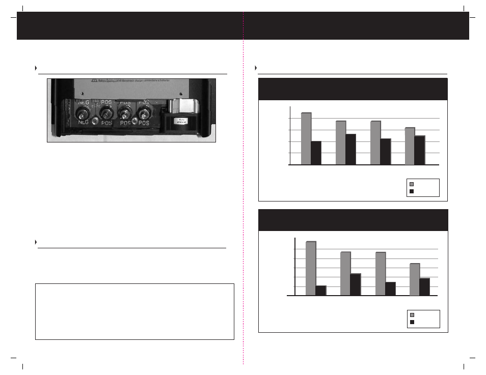
Shown Above: ProTech-i Plus model. The circuit board is clearly marked to identify the
polarity of each DC output connection.
Note: For your safety the charger is equipped with an internal temperature sensor that
will shutdown the charger in the event of thermal overload.
Note: Your ProTech-i charger is equipped with a fan, the fan will only run when needed.
The fan is temperature controlled and will only turn on when cooling is necessary.
4) Battery cables, connections and installation must comply with ABYC E-11 and A-31 standards.
To avoid risk of injury, fire or an explosion, ProMariner requires that when making a wire
connection to EACH BATTERY(s) Positive (+) Post, install the positive cable with an over current
protection fuse within 7 inches of connection to the battery or battery connection point. The
fuse rating should be at least 10 amps higher than the rated full output of the charger. See ABYC
E-11 for specific requirements. Over current protection within 7 inches of the charger’s negative
(-) DC output post is not required as the ProTech-i is self limiting and can not exceed its rated
current output. The internal fuses protect the unit against reverse polarity.
Typical 12 Volt DC Common Ground Installation Wiring
For 24 Volt installations, always make sure you have a 24 Volt Common Ground ProTech-
i Series Charger, and that your batteries are configured in series as a 24 Volt battery
bank or banks. Each 24 Volt bank will require a 24 Volt positive connection. Not sure
you know what voltage system you have on board your boat? Contact your local certified
ABYC marine electrical technician.
Installation Note: Preventing a short circuit of "live" DC Wires can be accomplished with the following proper steps:
1) Always connect the positive (+) DC output cables to the charger first.
2) Connect the remaining end of the DC cables to the required Protective fuse or DC breaker 4 to 7 inches
from the battery positive (+) post with the fuse out or the DC breaker in the off position.
3) Once all of the above wiring connections are completed and inspected, proceed with the protective fuses out of
the holder and or the protective breakers in the off position, make your final connections from the protective devices
to the Positive (+) posts of the associated Battery (s). Proceed to make the DC Ground Connection from the Charger
to the DC common Ground Buss followed by the Negative (-) Connections from the Battery (s) to the DC common
Ground Buss. When all wiring is completed install the protective fuses and or turn on the protective DC breaker(s).
See illustrations on page 12.
ProTech-i 12V User Programmable
Battery Type Charge Profile Chart.
Battery Type
V
olts DC
Absorption
Float
12.5
13
13.5
14
14.5
15
Flooded/AGM1
AGM 2
Sealed
Maintenance Free
13.5
13.8
13.6
14.7
14.4
14.4
GEL
13.7
14.1
ProTech-i 24V User Programmable
Battery Type Charge Profile Chart.
Battery Type
Volts DC
Absorption
Float
27
27.5
28
28.5
29
29.5
Flooded/AGM1
AGM 2
Sealed
Maintenance Free
27
27.6
27
.2
29.4
28.8
28.8
GEL
27.4
28.2
26.5