Setup and operation continued – ProMariner ProTech-i User Manual
Page 10
12
I n s t a l l a t i o n
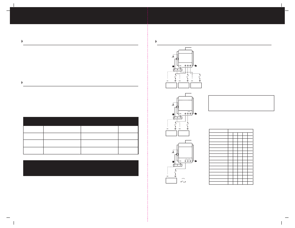
Typical 12 Volt DC Common Ground Installation Wiring Diagrams
(ABOVE) It is recommended that a jumper(s) be used between unused positive DC output
post(s) and a used positive DC post connected on your ProTech-i Series Charger. Please note
you can connect all three positive DC output posts together to form a single DC output on
your ProTech-i Series Charger.
All installations should be made in compliance with ABYC E-11 specifications for AC and DC
electrical systems on boats and specifications for A-31 Battery Chargers and inverters.
12 Volt 10 Amp Length Out and Back
Wire length 10' 15' 20' 25' 30'
AWG 14 12 10 10 10
12 Volt 15 Amp
Wire length 10' 15' 20' 25' 30'
AWG 12 10 10 8 8
12 Volt 20 Amp
Wire length 10' 15' 20' 25' 30'
AWG 10 10 8 6 6
12 Volt 25 & 30 Amp
Wire length 10' 15' 20' 25' 30'
AWG 10 8 6 6 4
12 Volt 40 Amp
Wire length 10' 15' 20' 25' 30'
AWG 8 6 6 4 4
24 Volt 20 Amp
Wire length 10' 15' 20' 25' 30'
AWG 14 12 10 10 10
Three Bank / 12 Volt DC Installation (FIG.1)
Connect DC cables to three of the positive DC output
posts as shown. Connect common ground negative
wire (as described below)
Two Bank / 12 Volt DC Installation (FIG.2)
Connect DC cables to two of the positive DC output
posts and use one jumper wire to connect the unused
post. Connect common ground negative wire (as
described below)
One Bank / 12 Volt DC Installation (FIG.3)
Connect to one positive DC output post and use two
jumpers to connect to the remaining unused posts. Connect
common ground negative wire (as described below)
Battery negative wires are installed separately to
the boat’s DC Negative / Ground buss bar (not provided).
Then a single connection is made to the charger. Note:
See page 14 for DC Chassis Ground connection details.
Table No.1 Wire gauges by amp rating and total
out and back wire distance as defined by the
length of the positive wire which must be added
to the length of the return negative wire.
Indicates Jumper Wire
Indicates a Fuse
Note:
bank 1
bank 2
bank 3
AC Input
DC Outputs
Common Negative
FIG.1
DC Chassis Ground
ProTech-i
bank 1
bank 2
AC Input
DC Outputs
Common Negative
FIG.2
DC Chassis Ground
bank 1
AC Input
DC Outputs
Common Negative
FIG.3
DC Chassis Ground
ProTech-i
ProTech-i
7
Selecting a Charging Profile & Understanding Battery Types
Selecting a Charging Profile and Understanding Battery Types
There are four primary types of batteries; Flooded (Lead-acid), AGM (Absorbed Glass
Mat) and GEL Cell (Gelled Electrolyte Lead-acid). Traditionally, the most common type of
batteries used are Flooded (Lead-acid batteries). The ProTech-i incorporates a 4th profile
for: Sealed Maintenance Free Batteries. A Sealed Lead Acid battery is one that does not
have removable caps to accommodate checking and maintaining electrolytic levels. This
type of battery is normally referred to as maintenance free.
Almost all GEL Cell Batteries will state that they are GEL Cell on the battery case or labels.
***If you are unsure as to what kind of battery you have, we recommend that you contact
the manufacturer of the battery.
NOTE: AGM (Absorbed Glass Mat) batteries are not GEL (Gelled Electrolyte Lead-acid)
batteries. AGM batteries are charged with a completely different charge profile when
compared to GEL batteries.
ProMariner battery maintainers are designed to keep batteries charged during the off
season to maintain the life of your battery. ProMariner maintainers keep a battery voltage
at a safe level so that a battery does not self discharge. For more information please visit
www.promariner.com or call 1-800-824-0524 for a dealer or retailer near you.
General recommendation for the Absorption Timer Switch is as follows:
Single Group 24 or Group 27…
2 Hours
Two Group 24, 27 or Single Group 31…
3 Hours
Single 4D or 8D...
4 Hours
Multiple 4 or 8Ds or Multiple…
4 Hours
***ACTUAL SWITCH SETTINGS ARE SHOWN ON PAGE 6***
Setup and Operation Continued
Battery Type
Battery
Information
Charging Voltage
Float Voltage
Flooded/AGM 1
14.7 VDC
13.5 VDC
29.4 VDC
27.0 VDC
Electrolyte
AGM 2
14.4 VDC
13.8 VDC
28.8 VDC
27.6 VDC
Sealed
Sealed
14.4 VDC
13.6 VDC
28.8 VDC
27.2 VDC
Sealed
GEL
14.1 VDC
13.7 VDC
28.2 VDC
27.4 VDC
Sealed
Charging Voltage
Float Voltage
12 Volt Models
24 Volt Models