Rail – NORSTAT Non-Contact Safety Switches User Manual
Page 2
SAFETY CONTROL UNIT
SAFETY SWITCHES
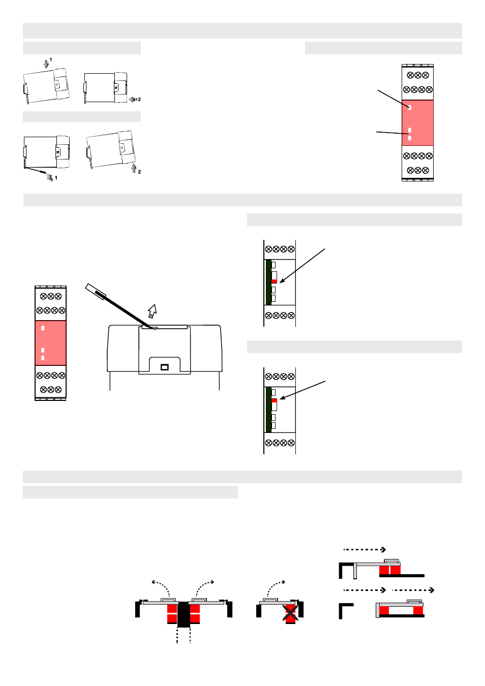
Mounting on 35mm DIN
Rail
Mounting the Safety Switches
Removal from 35mm DIN
Rail
Indication
CONTROL UNIT RESET
POWER
When power is
connected, the red
LED will be
illuminated
OUTPUT
When K1 & K2 are
illuminated green,
the outputs 13/14
& 23/24 will be
closed and 31/32
will open.
Internal switch is set to the
LOWER position
Circuit X1/X2 requires a
momentary N/O button to
initialise reset.
Internal switch is set to the
UPPER position
Circuit X1/X2 requires a link.
NOTE: Closed contacts on
K3 & K4 can still be moni-
tored
To remove lid, use small screwdriver in the lid recess as
shown and prise gently upwards.
Manual Reset
Automatic Reset
1
2
1
2
The control modules are de-
signed to be mounted in an IP55
(minimum) control cabinet.
The modules clip on to standard
35 mm symmetric DIN-Rail
To remove the modules, gently
lever out the DIN clip with a
small screwdriver as shown (1).
Tilt the unit in the direction (2)
and slip the unit off the DIN Rail
Minimum separation 50mm
between adjacent switches.
Do not use
safety switches
as a stop.
1 mm separation
when closed
provides the best
results.
DO NOT mount
on hinged side of
the guard.
EN1088 :
Hide the actuator where
possible.
50
mm
Minimum Gap
A
A
A
S
S
S
A
S
A
S
NORSTAT INC. 300 Roundhill Dr. Rockaway, NJ 07866
Tel: 973-586-2500 Fax: 973-586-1590 www.norstat.com