Kaman KD-2440 User Manual
Page 3
6
3
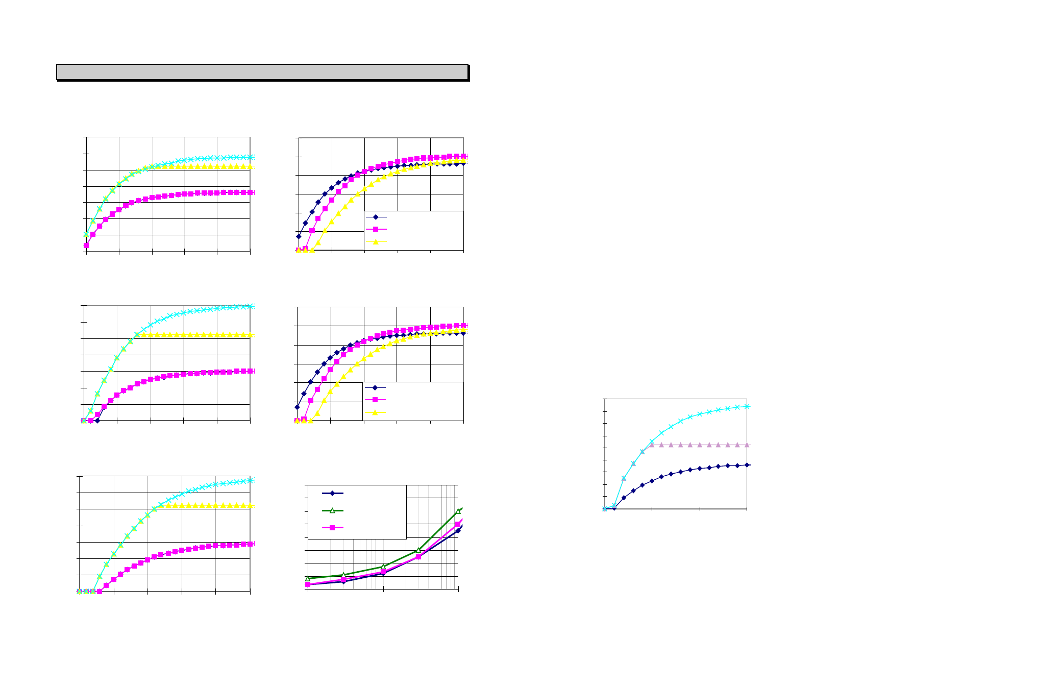
9C Sensor Response Data:
0
2
4
6
8
10
12
14
0
50
100
150
200
250
Aluminum Output for 12 & 24 Volt Input
Displacement, Mils
DC Ou
tp
u
t V
o
lt
ag
e
24 Vdc High Gain
12 Vdc High Gain
24 Vdc Low Gain
12 Vdc Low Gain
0
2
4
6
8
10
12
14
0
50
100
150
200
250
303 SS Output for 12 & 24 Volt Input
Displacement, Mils
DC Ou
tp
u
t V
o
lt
ag
e
24 Vdc High Gain
12 Vdc High Gain
24 Vdc Low Gain
12 Vdc Low Gain
0
2
4
6
8
10
12
14
0
50
100
150
200
250
Displacement, Mils
DC Ou
tp
u
t V
o
lt
ag
e
4130 Steel Output for 12 & 24 Volt Inputs
24 Vdc High Gain
12 Vdc High Gain
24 Vdc Low Gain
12 Vdc Low Gain
0
2
4
6
8
10
12
0
50
100
150
200
250
12V in Aluminum
12V in 303 Stainless
12V in 4130 Steel
Outputs at Medium Gain & 12 Volt Input
Displacement, Mils
DC Ou
tp
u
t V
o
lt
ag
e
0
2
4
6
8
10
12
0
50
100
150
200
250
24V in Aluminum
24V in 303 Stainless
24V in 4130 Steel
Displacement, Mils
DC Ou
tp
u
t V
o
lt
ag
e
Outputs at Medium Gain & 24 Volt Input
0.00
0.50
1.00
1.50
2.00
2.50
3.00
3.50
4.00
100
1000
10000
Bandwidth, Hz
D
ifferential N
o
ise, mV p-p
4130 Steel
304 Stainless
Aluminum
Example Output Noise @ 12Vdc Input, Mid
Gain, Medium Displacement
The signal is half-wave rectified and filtered to
obtain an analog voltage proportional to the target
position or displacement. The analog voltage
output can be varied by adjustment of the gain. The
input power is diode protected and regulated to
provide a clean low-noise signal. The output is
short-circuit current protected.
Adjustment and Calibration
The KD-2440 is instrumented with a ten volt
regulator to provide a clean repeatable output
signal. The input voltage must be maintained at a
minimum of twelve volts for the regulator to
function.
The gain (ratio of output voltage to target
displacement) is used to adjust the output slope
(output per displacement). When changing types of
target materials or power supply voltages, it will be
necessary to readjust the gain for the desired
output voltage.
The KD-2440 can easily be adjusted or “calibrated”
to obtain maximum output per displacement,
maximum range, or any variation in between. Note
that when the KD-2440 is adjusted for maximum
output per displacement, it is at a minimum usable
range, whereas a minimum gain gives a voltage
change throughout the largest displacement for the
same sensor, target, and range as depicted in the
following graph:
0
2
4
6
8
10
12
14
16
18
0
50
100
150
4130 Steel Output for 12 & 24 Volt Inputs
Displacement, Mils
DC Out
put
Volt
age
24 volt input with high gain
12 volt input with
high gain
12 or 24 volt input
with low gain
The minimum gain is defined as being the lowest
gain obtainable without pulling the circuit into
saturation. Minimum gain can be obtained by
setting the sensor displacement to a point within
the usable
range (preferably mid range), then
slowly decreasing the gain potentiometer
(clockwise) until the output saturates. At this point,
increase the gain slightly to a point just above
saturation (the output begins to change with a gain
increase).
Example Calibration
To maximize the output slope for an application using a
5CM sensor with a .010” offset and a range of .040”,
follow these steps:
1. Adjust the sensor / target to its maximum
displacement, plus the offset, plus approximately
20% of the range (.058”).
2. Adjust the gain potentiometer to its minimum point
(adjust clockwise until the analog output saturates)
3. Slowly increase the gain potentiometer (counter
clockwise) until it saturates at its maximum point.
this will be approximately two volts below the input
voltage.
4. At this point, the module is calibrated to a
maximum output per displacement condition. As
the sensor is moved toward the target from
approximately .058”, the output will decrease. If the
sensor / target displacement is increased beyond
.058”, the output will saturate at approximately two
volts below the input.
Switched Output Operation
The KD-2440’s switched output is a simple on / off
switch with a corresponding LED indicator lamp. The
switch is in a closed condition when the LED is
illuminated. The switch can be adjusted to trip
anywhere along the sensor range using the “Switch
Setpoint” potentiometer.
CLEANING
The KD-2440 is not designed to be immersed or
operated while immersed in liquids. Solvents may
damage electronics module, sensor, or power I/O
cable. Clean the unit with a damp cloth.
EMI PERFORMANCE
The KD-2440 conforms with the applicable standards
of Council Directive for Generic for Light Industrial and
Commercial Use. Under some EMI environments, at
specific frequencies, the KD-2440 unit may experience
a change in output voltage. In general, when exposed
to those environments covered by the EMC directive,
the user can expect less than 5% deviation of output.
Contact Kaman Instrumentation for
specific data or for
recommended solutions if you experience problems
with the KD-2440.
Home