Dwyer BTK2 User Manual
Page 3
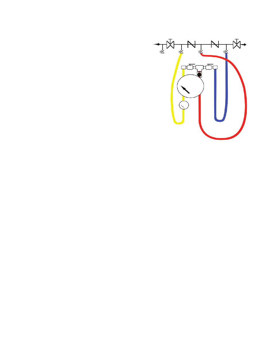
Double Check Valve Assemblies
Some field test procedures for testing double check valve assemblies require that
the number 1 shut-off valve be closed to accomplish the test. This procedure may
introduce debris such as rust into the valve that will impact against check valve
number 1 or number 2 and compromise the sealing quality. This potential problem
should be considered prior to the selection of the appropriate test method.
The following steps are performed utilizing the BTK2 without the need to shut off
number 1 shut-off valve. For the following steps, refer to figure 4.
Step 1 - Checking check valve number 1.
1. Verify that the number 1 shut-off valve is open. Shut-off number 2 shut-off valve.
2. Connect the high pressure hose (yellow) to test cock number 2.
3. Connect the low pressure hose (red) to test cock number 3.
4. Open test cocks 2 and 3.
5. Open high pressure side ball valve A on test kit bleeding the air from the high
pressure hose (yellow). Close the high pressure side ball valve A.
6. Open low pressure side needle valve B on test kit bleeding the air from the low
pressure hose (red). Close the low pressure side needle valve B.
Step 2 - Checking check valve number 2.
1. Connect the high pressure hose (yellow) to test cock number 3.
2. Connect the low pressure hose (red) to test cock number 4.
3. Open test cocks number 3 and 4.
4. Open high pressure side ball valve A on test kit bleeding the air from the high
pressure hose (yellow). Close the high pressure side ball valve A.
5. Open low pressure side needle valve B on test kit bleeding the air from the low
pressure hose (red). Close the low pressure side needle valve B.
6. Record the differential gage pressure reading. It should be a minimum of 1 psid.
7. Disconnect the hoses.
Check tightness of number 2 shut-off valve, both the check valves must be tight
and holding a minimum of 1 psid using the following procedure. Little or no
fluctuation of inlet supply pressure can be tolerated.
The testing is performed as follows:
1. Connect the high pressure hose (yellow) to number 2 test cock.
2. Connect the low pressure hose (red) to number 3 test cock.
3. Connect the vent hose (blue) to number 4 test cock.
4. Open test cocks numbers 2, 3, and 4.
5. Open high pressure side ball valve A on test kit bleeding the air from the high
pressure hose. Close the high pressure side ball valve A.
6. Open low pressure side needle valve B on test kit, bleeding the air from the low
pressure hose (red). Close the low pressure side needle valve A.
7. The differential gage pressure should read a minimum of 1 psid.
8. Open the high pressure side ball valve A and the bypass hose ball valve C on
the test kit. (This supplies high pressure water downstream of check valve number
2).
9. Close test cock number 2. (This stops the supply of any high pressure water
downstream of number 2 check valve). If the differential pressure gage reading
holds steady, the number 2 shut-off valve is recorded as being tight. If the
differential pressure gage drops to zero, the number 2 shut-off valve is recorded as
leaking.
With a leaking number 2 shut-off valve, the device is, in most cases, in a flow
condition, and the previous test readings taken are invalid. Unless a no flow
condition can be achieved, either through the operation of an additional shut-off
downstream, or the use of a temporary compensating bypass hose, accurate test
results will not be achieved. This completes the standard field test for a double
check valve assembly. Prior to removal of the test equipment, the tester should
ensure that they open number 2 shut-off valve thereby reestablishing flow. All test
data should be recorded on appropriate forms and the test kit drained of water.
MAINTENANCE/REPAIR
The Model BTK2 requires no routine maintenance, but should be routinely checked
for calibration. The Model BTK2 is not field serviceable and should be returned if
repair is needed. Field repair should not be attempted and may void warranty.
WARRANTY/RETURN
Refer to “Terms and Conditions of Sales” in our catalog and on our website. Contact
customer service to receive a Return Goods Authorization number before shipping
the product back for repair. Be sure to include a brief description of the problem
plus any additional application notes.
Figure 4 - Double Check Valve Assemblies
Te
st
co
ck
N
o.
1
No
. 1
s
hu
t-o
ff
va
lve
Te
st
co
ck
N
o.
2
Ch
ec
k
va
lve
N
o.
1
Te
st
co
ck
N
o.
3
Ch
ec
k
va
lve
N
o.
2
Te
st
co
ck
N
o.
4
No
.2
s
hu
t-o
ff
va
lve
Ball Valve A
Ball Valve C
Needle
Valve B
High Pressure
Hose (Yellow)
Low Pressure
Hose (Red)
Vent Hose
(Blue)