Dwyer BTK2 User Manual
Page 2
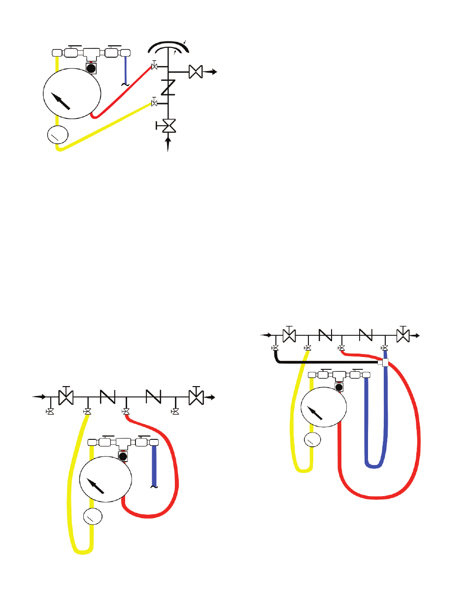
Reduced Pressure Principle Backflow Preventer
Field testing of a reduced pressure principle backflow preventer is accomplished
utilizing a differential pressure gage such as the BTK2 test kit. The device is tested
for three optional characteristics: i.e., (1) the first check valve is tight and maintains a
minimum of 5 psi differential pressure, (2) the second check valve is tight against
backpressure and (3) the relief valve opens at a minimum of 2 psi below inlet supply
pressure. Testing is performed as follows:
Step 1 - Refer to Figure 2
Test to ensure that the first check valve is tight and maintains a minimum pressure of
5 psi differential pressure using the following procedure. Perform with Ball Valve C
closed.
1. Verify that number 1 shut-off valve is open. Close number 2 shut-off valve. If there
is no drainage from the relief valve, it is assumed that the first check valve is tight.
2. Close all test kit valves.
3. Connect the high pressure hose (yellow) to test cock number 2.
4. Connect the low pressure hose (red) to test cock number 3.
5. Open test cocks number 2 and number 3.
6. Open high pressure side needle valve B on test kit bleeding the air from the high
pressure hose. Close the high pressure side ball valve A.
7. Open the low pressure side needle valve B on test kit bleeding air from the low
pressure hose (red). Close the low side needle valve B. Record the differential gage
pressure reading. It should be a minimum of 5 psid.
Step 2- Refer to Figure 3
Test to ensure that the second check valve is tight against backpressure using the
following procedure.
1. Leaving the hoses hooked up as in the conclusion of Step 1, connect vent hose
(blue) to test cock number 4.
2. Open test cock number 4, the high pressure ball valve A and the bypass hose ball
valve C on the test kit. (This supplies high pressure water downstream of check valve
number 2.) If the differential pressure gage reading drops and water comes out of the
relief valve, the second check valve is recorded as leaking. If the differential pressure
gage reading remains steady, and no water comes out of the relief valve, the second
check valve is considered tight.
3. To check the tightness of number 2 shut-off valve, leave the hoses hooked up the
same as at the conclusion of Step 2 (2), and then close test cock number 2. This stops
the supply of any high pressure water downstream of check valve number 2. If the
differential pressure gage reading holds steady, the number 2 shut-off valve is
recorded as being tight. If the differential pressure gage reading drops to zero, the
number 2 shut-off valve is recorded as leaking.
With a leaking number 2 shut-off valve, the device is, in most cases, in a flow
condition and the previous readings taken are invalid. Unless a no-flow condition can
be achieved, either through the operation of an additional shut-off downstream, or the
use of a temporary compensating bypass hose, accurate test results will not be
achieved.
Step 3 Check that the relief valve opens at a minimum pressure of 2 psid below inlet
pressure using the following procedure.
1. With the hoses hooked up the same as at the conclusion of Step 2 (3), slowly open
up the low pressure control needle valve B on the test kit and record the differential
pressure gage reading at the point when the water initially starts to drip from the relief
valve opening. This pressure reading should not be below 2 psid.
This completes the standard field test for a reduced pressure principle backflow
preventer. Before removal of the test equipment, the tester should ensure that they
open number 2 shut-off valve thereby reestablishing flow. Also, the test kit should be
thoroughly drained of all water to prevent freezing by opening needle valve B, and ball
valves A and C.
Figure 2 - Reduced Pressure Principle Backflow Preventer
Te
st
co
ck
N
o.
1
No
. 1
s
hu
t-o
ff
va
lve
Te
st
co
ck
N
o.
2
Ch
ec
k
va
lve
N
o.
1
Te
st
co
ck
N
o.
3
Ch
ec
k
va
lve
N
o.
2
Te
st
co
ck
N
o.
4
No
.2
s
hu
t-o
ff
va
lve
Ball Valve A
Ball Valve C
Needle
Valve B
High Pressure
Hose (Yellow)
Low Pressure
Hose (Red)
Vent Hose
(Blue)
Figure 3 - Reduced Pressure Principle Backflow Preventer
Te
st
co
ck
N
o.
1
No
. 1
s
hu
t-o
ff
va
lve
Te
st
co
ck
N
o.
2
Ch
ec
k
va
lve
N
o.
1
Te
st
co
ck
N
o.
3
Ch
ec
k
va
lve
N
o.
2
Te
st
co
ck
N
o.
4
No
.2
s
hu
t-o
ff
va
lve
Ball Valve A
Ball Valve C
Needle
Valve B
High Pressure
Hose (Yellow)
Low Pressure
Hose (Red)
Vent Hose
(Blue)
Temporary
Bypass Hose
(Black)
Figure 1 - Pressure Vacuum Breaker
Test cock
No. 2
Test cock
No. 1
Air inlet valve canopy
Loaded air inlet valve
No. 2 shut-off valve
Check valve
No. 1 shut-off valve
Ball Valve A
Ball Valve C
Needle
Valve B
Low
Pressure
Hose
(Red)
High Pressure
Hose (Yellow)
Vent Hose
(Blue)