Dwyer LVT1 User Manual
Dwyer Water boiler
Model LVT1 Digital programmable Indoor
Thermostat with Heat Pump
111213
Installation, Mounting:
Caution: Turn off model LVT1 and the electronic devices (e.g.
heater, cooler) which will be connected, and the electric
source before installation and maintenance. It is highly
recommended that the installation procedure is processed by
trained professional.
1. Installation location:
The Thermostat is restricted to be used indoors only. It should
be mounted on an inner wall about 1.5m above the floor at a
position where it is readily affected by changes of the general
room temperature with freely circulating air. Avoid mounting
above or near hot surfaces or equipment (e.g. TV, heater,
refrigerator). Avoid mounting where it will be exposed to
direct sunshine, drafts, or in a laundry room or other enclosed
space. Do not expose this unit to dripping or splashing.
2. Wiring:
- Be sure main switch is at the middle (OFF) position, and
fan switch is at the (FAN AUTO) position.
- Wire the proper cables at the terminal block according to
the circuit diagram.
- Afterward, push all cables back into the wall.
- Do not use metal conduit or cable provided with a metal
sheath.
- It is recommended to add fuse or protective device in the
line circuit.
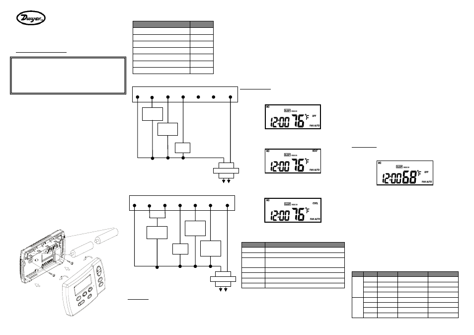
3. Mounting:
Using the accessory screws and wall anchors provided, mount
the thermostat with the key-hole at the back. The thermostat
should be mounted on the wall as shown in Figure 1.
Figure 1
4. Electrical Interface:
Terminals
Symbol
Switched Side, 24 VAC
R
Reversing Valve (Cool)
O
Reversing Valve (Heat)
B
Fan
G
Heater Output
W
Cooler Output
Y
Unswitched Side,24 VAC
C
Wiring diagram for thermostat:
Wiring diagram for heat pump thermostat (Compressor):
Feature list
●
Operates on 1 stage Heat and 1 stage Cool
●
2 programs (Mo-Fr, Sa-Su)
●
4 Separate time and temperature settings for each program
●
Heat and Cool set-points for each program
●
Low battery indicator
●
EEPROM stores heat and cool program settings
●
Temperature display in °F or °C
●
Temporary program override
●
Permanent program override
●
Short cycle protection
●
Adjustable filter usage counter
●
Adjustable energy usage counter
●
Adjustable temperature control span
●
LCD backlighting
●
Defrost function
User Interface
1. Slide switch select System Mode
OFF:
No Heating and Cooling will be activated at any temperature.
HEAT:
Heating will be activated when condition is met.
Changeover valve always stays at Heat side.
COOL:
Cooling will be activated when condition is met.
Changeover valve always stays at Cool side.
2. Push Buttons
Symbol
Description
▲
Up
▼
Down
PROG
Enter to Program & Permanent Override
mode, Release Temporary Override
TIME
Set time and date
TEMP
Read and Set temperature control options
USAGE
Read and Set System Usage time
RUN
Confirm and Return
3. Select Fan Mode
Use the Fan slide switch to select Fan mode.
FAN AUTO:
Fan turns on whenever Heating or Cooling is on.
(Depends on HE:ON / HG:OFF setting)
FAN ON:
Fan stays on all the time.
4. Jumpers
Remove the front plate, the jumpers are at the circuit board.
Reset the thermostat is required if the jumper is changed the
position.
1. Temperature unit selection (C/F)
Set temperature unit °F or °C. The program will be restore
to default setting, when the setting is changed.
2. HE-HG selection (HE/HG)
HE - fan auto control for electrical heat.
HG - fan auto control for gas heat.
3. Delay / No Delay Selection (D/ND)
Heater
Cooler
No delay
10 sec
4 mins
Delay
4 mins
4 mins
Choose the Delay option if compressor heat is connected.
Operation
Normal Mode
Time Setting
1. Press [TIME], day icon starts flashing. Use [▲] / [▼]
keys to set the day.
2. Press [TIME], hour digits start flashing. Use [▲] / [▼]
keys to set hour.
3. While hour digits are flashing, press [TEMP] key to toggle
between 12-hour and 24-hour time mode.
4. Press [TIME], minute digits start flashing. Use [▲] / [▼]
keys to set minute.
5. Press [RUN] to confirm time settings; Press [TIME] to loop
back to set minutes.
Programming
Below is the default program:
Event
Time
Heat
Cool
M
O
–
F
R
WAKE 6:00 AM
70 °F (21°C)
78 °F (26°C)
OUT
8:00 AM
62 °F (17°C)
85 °F (29.5°C)
BACK 6:00 PM
70 °F (21°C)
78 °F (26°C)
SLEEP 10:00 PM
62 °F (17°C)
82 °F (28°C)
S
A
–
S
U
WAKE 6:00 AM
70 °F (21°C)
78 °F (28°C)
OUT 10:00 AM
62 °F (17°C)
85 °F (29.5°C)
BACK 6:00 PM
70 °F (21°C)
78 °F (26°C)
SLEEP 11:00 PM
62 °F (17°C)
82 °F (28°C)
Cooler
Fan
Transformer
C
W
Y
G
B
O
R
24VAC
Heater
Compressor
Fan
Heat
Changeover
valve
Cool
Changeover
valve
Transformer
C
W
Y
G
B
O
R
24VAC