Dwyer instruments, inc – Dwyer QPC User Manual
Page 2
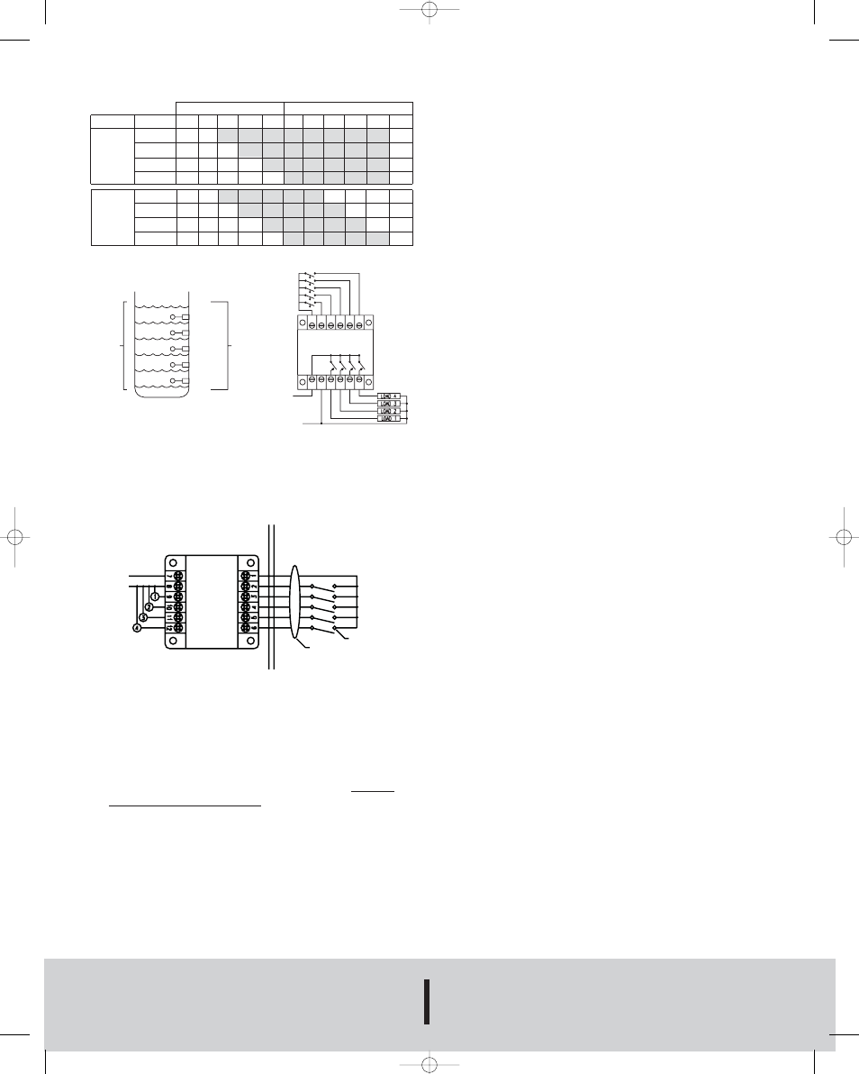
Increasing Level
Decreasing Level
A
B
C
D
E
F
E
D
C
B
A
Load 1
Off Off On
On
On On On On On On
Off
SOSO
Load 2
Off Off Off
On
On On On On On On
Off
Outputs Load 3
Off Off Off
Off
On On On On On On
Off
Load 4
Off Off Off
Off
Off On On On On On
Off
Load 1
Off Off On
On
On On On Off Off
Off
Off
FOFO
Load 2
Off Off Off
On
On On On On Off
Off
Off
Outputs Load 3
Off Off Off
Off
On On On On On Off
Off
Load 4
Off Off Off
Off
Off On On On On On
Off
DWYER INSTRUMENTS, INC.
Phone: 219/879-8000
www.dwyer-inst.com
P.O. BOX 373 • MICHIGAN CITY, INDIANA 46361, U.S.A.
Fax: 219/872-9057
e-mail: [email protected]
©Copyright 2007 Dwyer Instruments, Inc.
Printed in U.S.A.12/07
FR# R3-443592-01 Rev. 1
Figure A
SEQUENCING DESCRIPTION
SOSO - As the 3rd lag, 2nd lag, lag and lead switches open, the
loads remain energized. When the off switch opens, all four loads
de-energize simultaneously. If any switch fails to open, the loads
still de-energize when the off switch opens. The lead advances
one position each time the loads de-energize.
FOFO - When the 3rd lag switch opens, all four loads remain
energized. The 2nd lag switch opens next, and the lead load de-
energizes. When the lag switch opens, the lag load de-energizes.
Next, the lead switch opens and the 2nd lag load de-energizes.
Finally, the off switch opens and the 3rd lag load de-energizes. At
the end of each cycle, the lead advances one position for each
load energized during the cycle. For example: if loads one and two
cycle on and off, the lead will advance two positions. Load three
will be the lead load for the next cycle.
MAINTENANCE
Upon final installation of the Series QPC Quadraplex Pump
Controller, no routine maintenance is required. A periodic check of
the system calibration is recommended. The Series QPC is not
field serviceable and should be returned if repair is needed (field
repair should not be attempted and may void warranty). Be sure
to include a brief description of the problem plus any relevant
application notes. Contact customer service to receive a return
goods authorization number before shipping.
WATER
LEVEL
INPUT
LEVEL
SWITCH
F
E
D
C
B
A
3RD LAG
2ND LAG
1ST LAG
LEAD
OFF
HOT
NEUTRAL
3RD LAG
2ND LAG
1ST LAG
LEAD
OFF
1 2 3 4 5 6
7 8 9 10 11 12
EXCITATION TABLE
CONTROL DRAWING 194
HAZARDOUS LOCATION
CLASS I, GROUPS A, B, C, D; CLASS II,
GROUPS E, F, G, ; CLASS III
NON-HAZARDOUS LOCATION
HOT
NEUTRAL
CONTROL
VOLTAGE
LOADS
OFF
LEAD
LAG
2nd LAG
3rd LAG
SWITCH CONTACT SEE NOTE 3
INTRINSICALLY SAFE WIRING
SEE NOTES 1 AND 2
NOTES:
1. Maximum distance between unit and switch is 1000 feet.
2. All intrinsically safe wiring shall be separated from non-
intrinsically safe wiring. Refer to article 504 of the National
Electrical Code ANSI/ NFPA 70 for installation of intrinsically
safe wiring.
3. Switch contact shall be any non-energy strong or generating
mechanical switch type device containing no capacitance or
inductance.
Figure B
L-41 12/6/07 8:06 AM Page 2