Suggested tools, Required material, Identification – Badger Meter Gas Meter Endpoints User Manual
Page 3: Suggested tools 3, Required material 3, Identification 3
SUGGESTED TOOLS
VOM Multi-Meter (Analog)
59987-001
Coax Stripper
59989-001
Wire Cutting Pliers
59991-001
Wire Stripper
59993-001
Parallel Pliers
59983-001
TORX® #T-10 Driver
1/4" - 3/4" Vari-Bit (Newark 81N2636)
3/32" Transfer Punch
3/16" Transfer Punch
Double-Side Tape (3M 442PC)
62658-003
Table 1: Suggested tools
REQUIRED MATERIAL
OTEE:
N
Numbers in the first column correspond to the parts shown in
1
*Gasket (1)
62838-001
Parts marked with *
are included in the
Installation Kit
2
Outer cover
3
*TORX screws (4)
31820-026
4
*Gel connectors (2)
59761-001
5
*Ear clamp (1)
59759-001
*Ear clamp (1)
59759-002
—
Transmitter wire (Belden 9802) not shown
59604-003
Table 2: Required materials
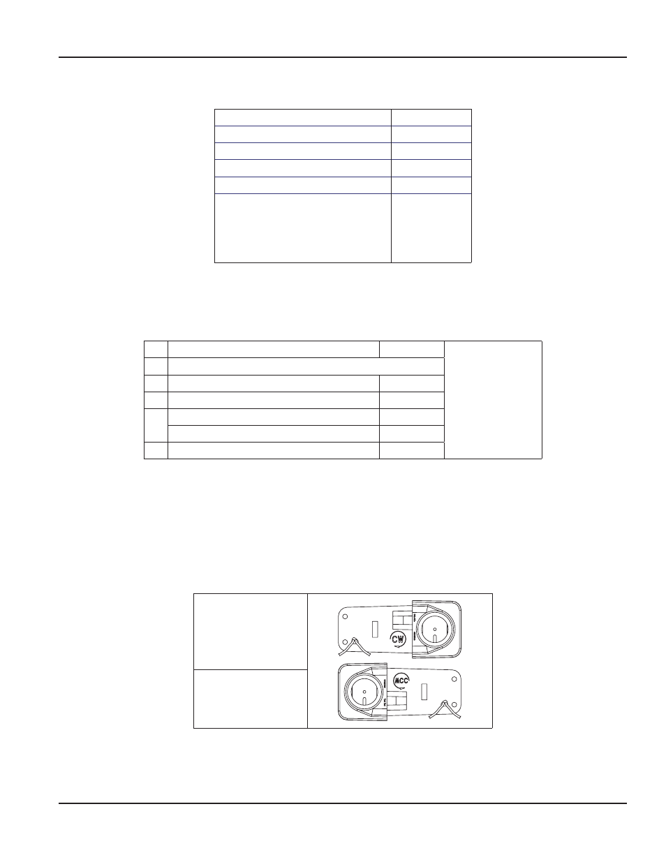
IDENTIFICATION
The Badger Meter Gas Recordall® Transmitter (Gas-RT) is available in two configurations: Clockwise Operation (CW) and
Counterclockwise Operation (CCW), as identified on the frame (looking toward the index), with the markings CW or CCW for
both configurations The Gas-RT should be installed so that the wire port is at the lower edge See
Red/Black: Used with TRACE® Remote and Pit Transponders, Itron® ERT® Remote and Pit Transponders, and ORION® Pit and
Remote Transponders
Identification-
clockwise operation
Identification-
counterclockwise
operation
Figure 1: CW & CCW operation identification
The Gas-RT is available for a wide variety of gas meters See
"Gas-RT Application Data" on page 6
for the correct unit
Before proceeding with installation, be certain the meter type conforms to the rotation for your Gas-RT and the proper Gas-RT
configuration, indicated above, has been supplied for the application
Installation Manual
Page 3
July 2014