Thermo Fisher Scientific EC/TDS/SaltTestr User Manual
Page 2
68X068050 05/05 Rev 1
+
-
INC Key
3 Bars indicates Battery is full (100%)
2 Bars indicates 50% of the battery life is left
1 Bar indicates 25% of the battery life is left
Blinking battery casing indicates the need to replace
batteries with fresh ones as specified by manufacturer
The sensor electrodes have short circuited.
Replacement sensor is not connected properly to the
tester during sensor replacement
Measured value or temperature value (for plus models)
exceeds its specified maximum or minimum value
Blinking ‘ATC’, ‘Or’ or ‘Ur’ indicates that there is a short
or open circuit at the built in temperature sensor
Calibration error due to temperature value not within the
specified range
Calibration error due to Conductivity/TDS/Salt value not
within the specified calibration standard range
Self-Diagnostic Messages
E r
E r
E r
E r
E r. 1
. 1
. 1
. 1
. 1
Low battery
indicator
Or / Ur
Or / Ur
Or / Ur
Or / Ur
Or / Ur
(Still)
Over range /
Under range
signal
ATC / Or /
ATC / Or /
ATC / Or /
ATC / Or /
ATC / Or /
Ur
Ur
Ur
Ur
Ur (Blinking)
E r
E r
E r
E r
E r. 0
. 0
. 0
. 0
. 0
Error
Message
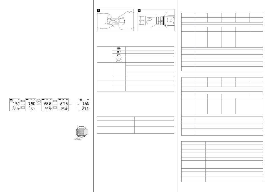
Electrode Replacement
You can replace the electrode module at the fraction of the cost of a new tester. When the tester fails
to calibrate or gives fluctuating readings in calibration standards, you need to change the electrode.
1. With dry hands, grip the ribbed tester collar with electrode facing you. Twist the collar counter
clockwise (see picture A). Save the ribbed tester collar and O-ring for later use.
2. Pull the old electrode module away from the tester.
3. Align the four tabs on the new module so that they match the four slots on the tester (see
picture B).
4. Gently push the module onto the slots to sit it in position. Push the smaller O-ring fully onto
the new electrode module. Push the collar over the module and thread it into place by firmly
twisting clockwise.
Note: It is necessary that you recalibrate your tester prior to measurement after an electrode
replacement.
Figure 7: Removal of collar from tester
Applications
Water quality testing • pools • aquaculture • hydroponics • ecology studies • water and
wastewater treatment • boilers • labs and more!
Accessories
Item
Order Code
ECTESTR, TDSTESTR & SALTESTR
TDSSENSOR
replacement sensor
ECTESTR+ & TDSTESTR+
TDSSENSORPLUS
replacement sensor
Warranty
The waterproof testers are warranted to be free from manufacturing defects for 1 year and
electrode module for 6 months, unless otherwise specified. If repair, adjustment or replacement
is necessary and has not been the result of abuse or misuse within the time period specified,
please return the tester - freight prepaid - and correction will be made without charge. Out of
warranty products will be repaired on a charge basis.
Return of Items
Authorization must be obtained from your distributor before returning items for any reason.
When applying for authorization, please include information regarding the reason the item(s) are
to be returned.
Note: We reserve the right to make improvements in design, construction and appearance of
products without notice. Prices are subject to change without notice.
Large Screen
Large Screen
Large Screen
Large Screen
Large Screen
E C T e s t r l o w
E C T e s t r l o w
E C T e s t r l o w
E C T e s t r l o w
E C T e s t r l o w
E C T e s t r l o w +
E C T e s t r l o w +
E C T e s t r l o w +
E C T e s t r l o w +
E C T e s t r l o w +
E C T e s t r h i g h
E C T e s t r h i g h
E C T e s t r h i g h
E C T e s t r h i g h
E C T e s t r h i g h
E C T e s t r h i g h +
E C T e s t r h i g h +
E C T e s t r h i g h +
E C T e s t r h i g h +
E C T e s t r h i g h +
E C T e s t r p u r e +
E C T e s t r p u r e +
E C T e s t r p u r e +
E C T e s t r p u r e +
E C T e s t r p u r e +
EC Tester
EC Tester
EC Tester
EC Tester
EC Tester
Range
0 to 1990 uS/cm
0 to 1999 uS/cm
0 to 19.90 mS/cm
0 to 19.99 mS/cm
0 to 199.9 uS/cm
Resolution
10 uS/cm
1 uS/cm
0.10 mS/cm
0.01 mS/cm
0.1 uS/cm
Accuracy
+/- 1% FS
Calibration point
1 point (± 50% window from factory default)
Calibration
200 to 1990
200 to 1999
2.00 to 19.90
2.00 to 19.99
20.0 to 199.9
Standard Range
uS/cm
uS/cm
mS/cm
mS/cm
uS/cm
Temperature
NA
Yes
NA
Yes
Range in °C
0.0 to 50.0°C
0.0 to 50.0°C
Range in °F
32.0 to 122°F
32.0 to 122°F
Resolution
0.1°C (0.1°F)
0.1°C (0.1°F)
Accuracy
±0.5°C (±0.9°F)
±0.5°C (±0.9°F)
Calibration point
1 point
1 point
Calibration Window
± 5°C (± 9°F)
± 5°C (± 9°F)
from factory default
from factory default
ATC
0 to 50°C
Temp Coefficient
2% per °C
Normalization Temp
25.0°C
Auto Off
8.5 minutes after last key press
Operating Temp
0 to 50°C
Power Battery
4 X 1.5V”A76" micro alkaline battery
Battery Life
>150 hrs
LCD Display
Custom Dual Display27mm(H)X21mm(W)
Dimensions
Tester: 16.5 cm X 3.8 cm; 90g
Weight
Boxed: 22cm X 6cmX 5cm; 170 g
ECTestr Specifications
TDSTestr Specifications
Large Screen
Large Screen
Large Screen
Large Screen
Large Screen
T D S T e s t r l o w
T D S T e s t r l o w
T D S T e s t r l o w
T D S T e s t r l o w
T D S T e s t r l o w
T D S T e s t r l o w +
T D S T e s t r l o w +
T D S T e s t r l o w +
T D S T e s t r l o w +
T D S T e s t r l o w +
T D S T e s t r h i g h
T D S T e s t r h i g h
T D S T e s t r h i g h
T D S T e s t r h i g h
T D S T e s t r h i g h
T D S T e s t r h i g h +
T D S T e s t r h i g h +
T D S T e s t r h i g h +
T D S T e s t r h i g h +
T D S T e s t r h i g h + T D S T e s t r p u r e +
T D S T e s t r p u r e +
T D S T e s t r p u r e +
T D S T e s t r p u r e +
T D S T e s t r p u r e +
TDS Tester
TDS Tester
TDS Tester
TDS Tester
TDS Tester
Range
0 to 1990 ppm
0 to 1999 ppm
0 to 10.00 ppt
0 to 10.00 ppt
0 to 199.9 ppm
Resolution
10 ppm
1 ppm
0.10 ppt
0.01 ppt
0.1ppm
Accuracy
+/- 1% FS
TDS Factor
0.4 to 1.0
Calibration point
1 point (± 50% window from factory default)
Calibration
200 to 1990
200 to 1999
1.00 to 10.00 ppt
20.0 to 199.9
Standard Range
ppm
ppm
ppm
Temperature
NA
Yes
NA
Yes
Range in °C
0.0 to 50.0 °C
0.0 to 50.0 °C
Range in °F
32.0 to 122 °F
32.0 to 122 °F
Resolution
0.1 °C (0.1°F)
0.1 °C (0.1°F)
Accuracy
±0.5 °C (±0.9 °F)
±0.5 °C (±0.9 °F)
Calibration point
1 point
1 point
Calibration Window
± 5°C (± 9°F)
± 5°C (± 9°F)
from factory default
from factory default
ATC
0 to 50°C
Temp Coefficient
2% per °C
Normalization Temp
25.0°C
Operating Temp
0 to 50°C
Power Battery
4 X 1.5V”A76" micro alkaline battery
Battery Life
>150 hrs
LCD Display
Custom Dual Display27mm(H)X21mm(W)
Dimensions
Tester: 16.5 cm X 3.8 cm; 90g
Weight
Boxed: 22cm X 6cmX 5cm; 170 g
SALTTestr Specifications
Large Screen TDS Tester
SALTTESTR
Range
0 to 10.00 ppt
Resolution
0.10 ppt
Accuracy
+/- 1% FS
Calibration point
1 point (± 50% window from factory default)
Calibration Standard Range
1.00 to 10.00 ppt
ATC
0 to 50°C
Temperature Coefficient
2% per °C
Normalization Temperature
25.0°C
Operating Temperature
0 to 50°C
Power Battery
4 X 1.5V”A76" micro alkaline battery
Battery Life
>150 hrs
LCD Display
Custom Dual Display27mm(H)X21mm(W)
Dimensions
Tester: 16.5cm X 3.8cm; 90g
Weight
Boxed: 22cm X 6cm X 5cm; 170g
Temperature Calibration (Only for PLUS Models)
Temperature calibration need not be performed every time, unless the temperature reading differs
from that of an accurate thermometer. If temperature calibration is performed, Conductivity/TDS/Salt
calibration is mandatory.
From the measurement mode,
1. Press the °C/°F button to select the desired temperature mode (Celsius or Fahrenheit).
2. Dip the tester into a solution of known temperature and allow time for the in built temperature
sensor to stabilize.
3. Press either the INC or DEC key to bring the tester to the calibration mode.
Note: At this stage, if the Conductivity/TDS/Salt reading is outside the specified range (showing Or
or Ur), the tester will show an error message of “Er.1”. You can still proceed with the temperature
calibration by continuing with step 4 or if the °C/°F button is not pressed within 2 seconds, the tester
will exit the calibration mode and return to the measurement mode.
4. Immediately press the °C/°F button to switch to the temperature calibration mode. The upper
display shows the current measured temperature reading based on the last set offset and the
lower display shows the current measured temperature reading based on factory default calibration.
5. Use the INC and DEC key to adjust the upper temperature reading to the known temperature value.
6. Wait for 5 seconds for the tester to automatically confirm the temperature calibration value by
displaying “CO” and return to the measurement mode.
Note: To exit this program without confirming the calibration, press the °C/°F button or the HOLD
button before the automatic confirmation takes place.
Note: The tester will exit calibration mode with “Er.0” message if the temperature is outside the 0 to
50°C range. Please refer to information under ’Self Diagnostic Messages’.
Notes: The temperature calibration window is +/- 5°C (+/- 9°F) from the default temperature reading.
Figure 6: Example of a temperature calibration sequence
Changing Batteries
1. Open the battery compartment lid (with attached lanyard loop).
2. Remove old batteries; replace with fresh ones. Note polarity
(shown in diagram below).
INC
DEC
INC
DEC
After 5 sec,
“CO” is
displayed
signifying
automatic
confirmation
Roate collar
away from you
Ribbed collar
Large O-Ring
Electrode Module
Small O-Ring
Small Tab
Large Tab
Insert Electrode Module