Ar ch ive d – Seametrics TX100-200-SERIES v.1 User Manual
Page 3
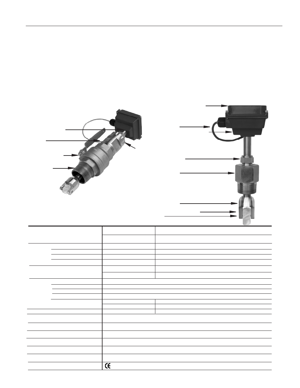
Rotor
Rugged cast aluminum housing
18 Foot Cable
Modular electronics (optional)
• rate/total/pulse/4-20 mA
• blind 4-20 transmitter
• pulse divider
Compression nut
for easy adjustment, secure locking
Adapter fitting
with 1-1/2” NPT threads
Rotor housing
Removable jewel bearings
TX101/201
Adapter fitting
with 2” NPT threads
Full-port 2” ball valve
for sensor removal
2” Adapter
removes to mount
hot-tap machine
3/4” diameter tubing
for low insertion force
TX115/215
Locking collar
TaBlES aND DIaGRaMS
Page 1
GENERal INfORMaTION
The TX100/200-Series are adjustable depth insertion turbines
that come in brass or 316 stainless models to fit 3” to 48”
pipe. Installation fittings are standard 1-1/2" (101/201) or 2”
(115/215) FNPT. Fittings such as saddles and weldolets may
be purchased either locally or from Seametrics.
Ruby bearings and a non-drag pickoff give these adjustable
insertion turbine flow sensors a wide flow range and long life.
A sensor detects the passage of miniature magnets in the ro-
tor blades. The resulting square-wave signal can be sent for
hundreds of feet without a transmitter, over unshielded cable.
This signal can be connected directly to many PLC’s and other
controls without any additional electronics.
If desired, a modular system of electronics can be installed
directly on the flow sensor or mounted remotely. The FT415
(battery powered) or FT420 (loop powered) provides digital rate
and total display, as well as programmable pulse; the FT420
also provides a 4-20 mA analog output. The AO55 is a blind
analog (4-20 mA) transmitter. Programmable pulse for pump
pacing is available with the PD10.
The “hot-tap” models (TX115/215) can be installed or serviced
without shutting down the line by means of a 2” full-port isola-
tion valve that comes with a nipple for installation on the pipe
fitting. In most circumstances, no special tool is required.
fEaTURES
SPEcIfIcaTIONS*
Standard
Micropowered (-04 Option)
6-40 Vdc/< 2 mA
3.5-16 Vdc/60 µA @ 3.5 Vdc
Magnetoresistive
Magnetoresistive
Current Sinking Pulse
Current Sinking Pulse
100 mA max
2 mA max
3-40 Vdc
≤ Supply Voltage
TX101/115
TX201/215
3” - 12” (50 - 300mm)
12” - 35” (300 - 890mm)
Cast aluminum
Brass or 316 SS
PVDF standard
Nickel-bound tungsten carbide/Ruby
TX101/201
TX115/215
None
Bronze (316SS optional)
1-1/2” NPT
2” NPT
0.5 - 30 feet/sec (0.15 - 9.14 meter/sec)
+/-1.5% of full scale
200˚ F (93˚ C)
200 psi (14 bar)
0.44 x pressure in pipe
#22 AWG 3-con, 18’ (6m); 2,000’ (650m) maximum cable run
Mark (Standard Power Only)
Power Source
Supply Voltage/current
Sensor
Type
Output
Sinking current
External Pull-up Resistor
Pipe Size
Materials Housing
Sensor Body
Rotor
Shaft/Bearings
Isolation Valve
fitting Size
flow Range
accuracy
Maximum Temperature
Maximum Pressure
Insertion force
cable
Regulatory
*Specifications subject to change. Please consult our website for the most current data (www.seametrics.com).
Note: For larger pipe sizes contact factory
AR
CH
IVE
D