Ar ch ive d, Pc1 application diagram – Seametrics PC2 User Manual
Page 2
+
-
24VDC
115VAC
* *
D I R E C T P L U G - I N
C L A S S 2 T R A N S F O R M E R
U
L
U
L
I / P : 1 2 0 V A C 6 0 H z 1 4 W
O / P : 1 2 V D C 5 0 0 m A
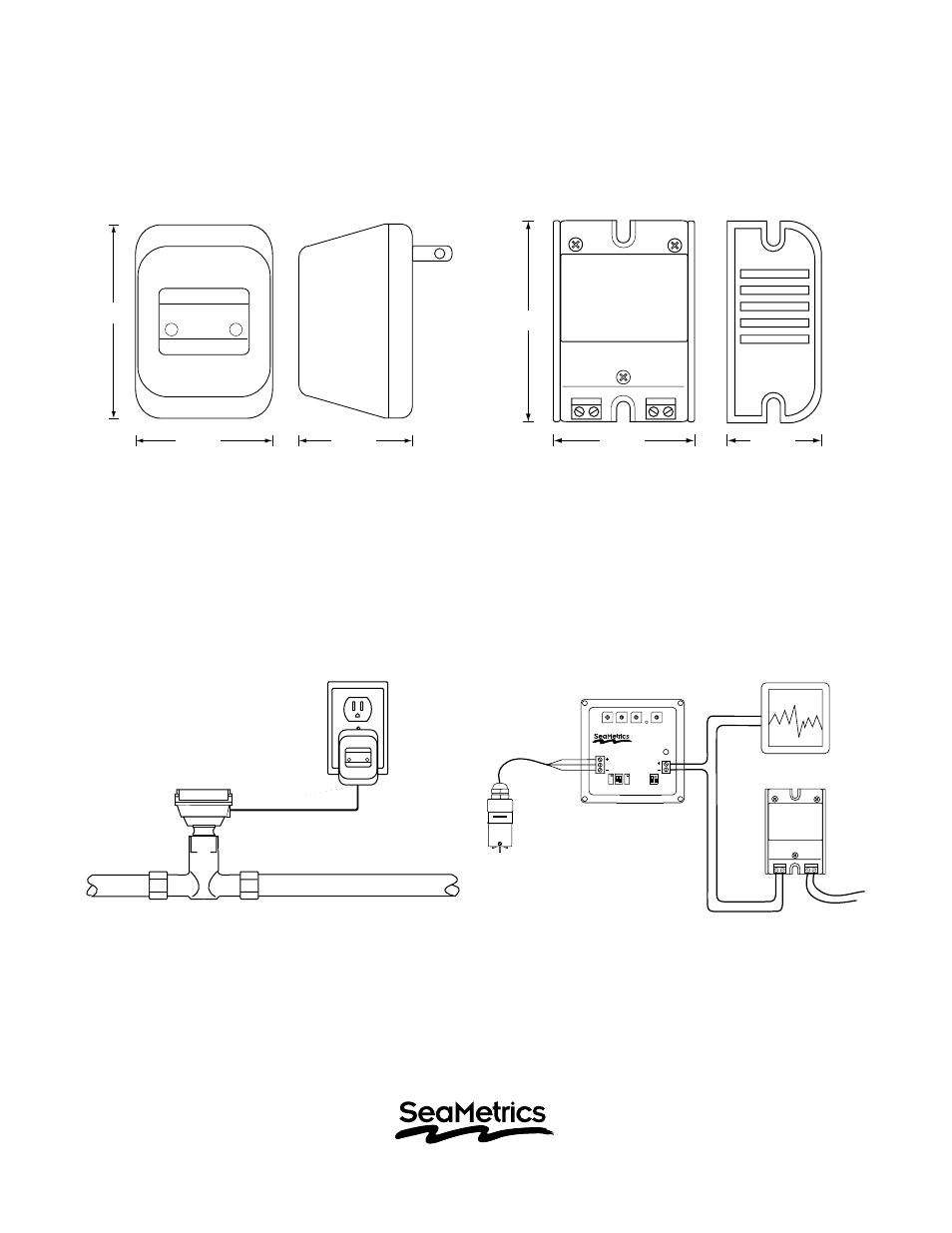
PC1 Dimensions
PC2 Dimensions
PC2 Application Diagram
20419 80th Ave. So., Kent, WA 98032 USA
Phone: 253-872-0284 Fax: 253-872-0285
www.seametrics.com 1-800-975-8153
PC1 Application Diagram
2.99"
1.40"
2.20"
1.90"
2.20"
3.19"
D I R E C T P L U G - I N
C L A S S 2 T R A N S F O R M E R
U
L
U
L
I / P : 1 2 0 V A C 6 0 H z 1 4 W
O / P : 1 2 V D C 5 0 0 m A
0
9
8
7
6
5
4
3
2
1
0
9
8
7
6
5
4
3
2
1
0
9
8
7
6
5
4
3
2
1
0
9
8
7
6
5
4
3
2
1
AO55
Frequency
Power
Sensor
4-20 mA
-
+
Recording or
Control Device
PC2 Power Supply
Sensor
AO55
4-20 mA Transmitter
+
-
24VDC
115VAC
* *
FT420 Indicator
PC1 Power Supply
2 of 2
AR
CH
IVE
D
This manual is related to the following products: