Figure 10 – Allied Air Enterprises (2 User Manual
Page 12
Page 12 of 14
506248-01
Issue 0902
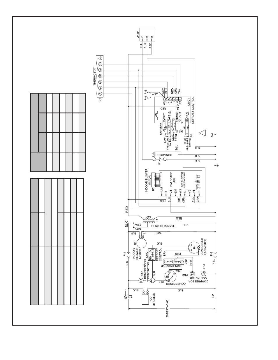
Connection Diagram
Single Phase – V
ariable S
peed Motor
P/N 48374-001
Figure 10
DIAGNOSTIC DISPLA
Y
Note:
Because the pressure s
witches are monitored only when "Y1" (Input) is activ
e
, the
code f
or pressure s
witch open will not be seen when "Y1" is off
.
Instead, the
“Nor
mal Oper
ation" or
“Anti-Shor
t Cycle Loc
k
out”
code will be seen.
When a pressure s
witch opens and causes a shor
t cycle loc
k
out, the pressure s
witch-open
code will be seen until it closes
, then the shor
t cycle loc
k
out code will flash unless it has
already e
xpired.
Mode
G
reen
LE
D
Re
d
L
ED
No
P
o
w
e
r
to
Board
O
ff
Off
Nor
m
al
Oper
ation/
P
o
w
e
r
to
Board
Sim
u
ltaneous
Slo
w
Flash
Anti-Shor
t
C
ycle
Loc
k
out
Alter
nating
S
lo
w
F
lash
Lo
w
P
ressure
Switch
F
ault
Off
Slo
w
Flash
Lo
w
P
ressure
Switch
Loc
k
out
Off
O
n
High
Pressure
Switch
F
ault
Slo
w
Flash
Off
High
Pressure
Switch
Loc
k
out
On
Off
Unit
F
a
c
tor
y
S
hipped
S
e
tt
ings
AD
J
U
S
T
HE
A
T
C
OOL
24
NORM
B
B
30
NORM
A
A
36
NORM
A
A
42
NORM
C
C
48
NORM
B
B
60
NORM
A
A
BLOWER SPEED CHAR
T
DIA
GNOSTIC
MODULE
CONNECTION MUST BE
JUMPERED
WHEN PRESSURE
SWITCH IS NO
T USED
.
2
NO
TE - If an
y of the or
iginal wire is replaced,
the same siz
e and type wire m
ust be used.
Use copper conductor only
, min.
75°C wire
.
W
ARNING - Electr
ic shoc
k hazard.
Unit m
ust
be g
rounded in accordance with national and
local codes
.
Line v
oltage field installed.
W1 &
W2 can be used to stage electr
ic heat
accessor
y on 15 & 20kW models
.
5, 7.5, & 10kW heater accessor
ies function
off
W1 only
.