Ar ch ive d, Includes dates before 1 1/06), Em series – Seametrics EM 101 v.1 User Manual
Page 2
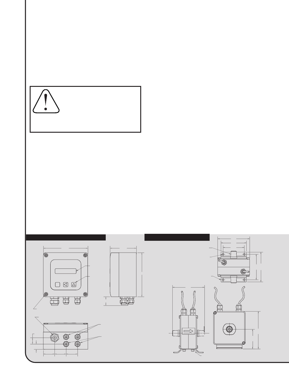
BACKLIT LCD,
2 LINES OF 16
CHARACTERS
KEYPAD
SWITCHES,
TACTILE
CAPTIVE PLASTIC COVER SCREW (4)
4.93
SET
POWER (CORD INCLUDED BUT NOT SHOWN)
CUSTOMER CABLING
(OUTPUTS, ALARMS)
SENSOR CABLES (2)
.71
.59
1.25
1.25
1.25
1.00
4.93
2.92
PVDF PLASTIC
3/8 NPT MALE
FITTING, 2
PLACES
.218 DIA,
4 HOLES
REMOVABLE
MOUNTING
BRACKET
3.75
3.00
2.50
3.00
3.50
3.75
10-24 UNC SCREWS;
SEE GROUNDING INSTRUCTIONS
6 FT. LONG
CONTROL CABLE
TO CONTROL
HOUSING
2.30
4.40
C O N T R O L H O U S I N G
EM SERIES
101 MAGNETIC FLOW METER INSTRUCTIONS
www.seametrics.com
Mounting. Mount the control housing to a secure
surface with screws or bolts. To gain access to the
mounting holes, remove the front cover. The mounting
holes are directly under the front cover screws. The
primary element is supplied with a foot bracket, which
can be attached to a secure surface. Alternatively, the
unit can be supported by the piping and the foot bracket
can be removed.
Connections. The unit ships with the coil activation and
signal leads already connected to the control housing. To
connect output signal or alarm relay leads, remove the
front cover. See the “Connections” diagram. Power
connection uses a standard power cord. If conduit
connection is required, remove the cord and strain relief
and use the strain relief hole for a conduit connector.
Grounding. Important: For proper operation, one or both
of the ground lugs must be well connected to a good
INSTALLATION
CAUTION:
Although this meter has an
empty pipe detection function, under
certain conditions of empty or
partially-full pipe the meter may read
a flow when there is none. If this is a
hazardous condition, mount the meter in such a way
as to ensure the meter will always be full of liquid.
quality earth ground. (The ground lugs also retain the
foot bracket). See the Grounding diagram on page 4.
All magmeters come with a 12 feet ground wire attached.
OPERATION
Display. The flow rate is displayed in the time and
volume units which have been selected (liters/min, for
example). The cumulative total flow is displayed in the
chosen units, up to eight digits. It then resets to zero
and begins again.
Outputs. The analog output which has been chosen
varies continuously with the flow. If the output is too
“jumpy” (changes too frequently), it can be damped
either by increasing the averaging time (see the “Fast
Analog Output” setting) or by selecting “Disabled”
under Fast Analog Output and increasing the amount
of damping using the Low Pass Filter setting. The pulse
output will produce a 50% duty cycle pulse at the
volume intervals for which it is set - one pulse per
liter, for example. Note that since each pulse consists
of equal times on and off, if the interval between
pulses is large the pulse may remain in the “on”
condition for several seconds. The relay alarm output
will only energize if the flow goes above (high) or
below (low) the flow alarm setting. The alarm relay
will remain energized until the flow exceeds the
setpoint by .25% (hysteresis).
P R I M A R Y E L E M E N T
MOUNTING PATTERN
AR
CH
IVE
D
(Includes Dates Before 1
1/06)