General information, Installation and connection, Specifications – Seametrics PT35 User Manual
Page 2
Mounting.
Use a secure surface that will accept screws.
Remove the front clear cover by use of the thumb screws to
access the mounting holes at the four corners. Using the box
as a template, mark the centers of the holes with a pencil and
drill. Insert screws through the four corner holes and tighten.
Connect the Meter.
Because the PT35 comes standard with
a built-in meter connector, the simplest method of connect-
ing your Seametrics meter to the PT35 is to order a mating
“Seametrics connector” pre-installed on your meter or flow
sensor. If your meter does not have a Seametrics connector,
there are three alternatives: 1) Any wire ends can be con-
nected to the PT35 terminal block (see Connections diagram
at right). 2) A cable-with-connector can be factory-ordered
and field-wired to your meter. 3) A connector can be factory-
ordered and field-installed on your meter output cable (see
Connector Field Installation diagram below).
GENERAL INFORMATION
The PT35 digital counter-timer is designed to be used with
Seametrics (or similar) meters and flow sensors that produce a
pulse signal. It is typically used in water treatment and chemical
dosing applications, most often in cooling towers and boilers.
The PT35 serves as either a single or a dual timer, depending
on whether one or both of its independent accumulators and
timed outputs are used.
In single timer applications, one accumulator counts pulses
coming from the meter. When a pre-set number of pulses has
been reached, output power turns on for a set time, and then
the cycle repeats.
In dual timer applications (typically, one chemical feed and one
water bleed), both accumulators and timers are set to operate
independently with input from a single meter. A sequential
function can be selected to lock one timer out while the other
is operating. This prevents feed and bleed from occurring
simultaneously.
The PT35 can be used with dry contact meters (e.g. Seametrics
MJR meters), contacting-head meters with solid-state pickups
(e.g. Seametrics MJE meters), or insertion flow sensors (e.g.
Seametrics IP, TX, and EX Series).
Ground
Neutral
Hot
NO NC N G
NO NC N G
Hot Normally Open
Hot Normally Closed
Neutral
Ground
Ground
Neutral
Hot Normally Closed
Hot Normally Open
H V G
P
G
S
V
OUTPUT 1
OUTPUT 2
3AG-10A-SB
Fuse
POWER
GND
SIGNAL
EXTERNALLY-PACED
METERING PUMP
DRY CONTACT
TYPE METER
GND
GND
SIGNAL
SIGNAL
+12 Vdc
+12Vdc
PUMP+
SOLID STATE
TYPE METER
SOLID STATE
TYPE METER
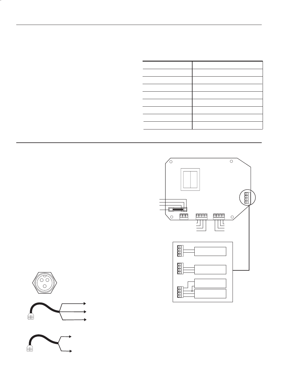
INSTALLATION and CONNECTION
Connector Field Installation
3
2
1
1 POWER GND
2 INPUT SIGNAL
3 POWER OUTPUT +12 Vdc
INPUT CONNECTOR
To Connector Pin 1
BLACK
WHITE
RED
To Connector Pin 2
To Connector Pin 3
To Connector Pin 1
To Connector Pin 2
Hall-effect or transistor switch
Dry contact
Connect the Load.
Two output cords are provided for connec-
tion of 115 Vac loads. The unit can be hard-wired if necessary,
using the terminals inside.
Connect Power.
A power cord is provided. Connect by plugging
in to any standard grounded outlet. (See Connections Diagram
above for conduit connection.)
115 Vac
12 Vdc
115 Vac
5” x 7” polycarbonate
1 - 9999 pulses
1 - 9999 seconds
1000 Hz
5 A resistive @ 115 Vac, or 1/4 HP
32˚ - 130˚ F (0˚ - 55˚ C)
Power
Sensor Power
Output (2)
Enclosure
Accumulator Range
Timer Range
Maximum Input Frequency
Relay Contact Rating
Temperature
SPECIFICATIONS*
PT35 Connections Diagram
Input Connections
PT35
*Specifications subject to change • Please consult our website for current
data (www.seametrics.com).