Connection diagrams, 12 3a, 9b 6 7 8 a-c – Seametrics MJN-Series User Manual
Page 4: Diagram 1: single sensor diagram 2: dual sensor
LT-103230-081613
08/16/2013
Seametrics Incorporated • 19026 72nd Avenue South • Kent, Washington 98032 • USA
(P) 253.872.0284 • (F) 253.872.0285 • 1.800.975.8153 • www.seametrics.com
CONNECTIONS, MAINTENANCE and REPAIR
Page 4
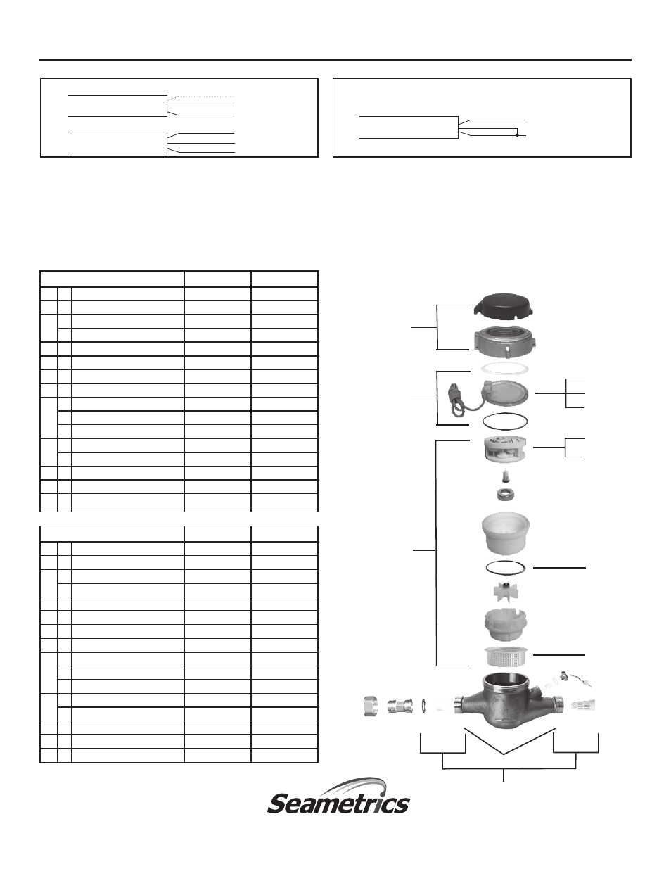
MJN-SERIES PARTS
1½”
2”
1
Lid and Hinge Pin Assembly
101070
101070
2
Lens Gasket Assembly
101085
101085
3
a
Internal Assembly (gallons)
101075
101076
b
Internal Assembly (cubic feet)
101079
101080
4
Coupling Assembly (incl 2 sets)
103239-150
103239-200
5
Coupling Gasket Assembly (incl 2)
103240-150
103240-200
6
Lens
101004
101004
7
Sensor Screw
101045
101045
8
a
Single Reed Switch Sensor (MJR)
100980
100980
b
Double Reed Switch Sensor (MJR)
100993
100993
c
Single Hall-Effect Sensor (MJE)
101065
101065
9
a
Register (gallons)
100999
101000
b
Register (cubic feet)
101008
101009
10
Internal Strainer
101044
101044
11
Tubular Strainer
101031
101032
12
Register Gasket
102228
102228
INTERNAL PARTS REPLACEMENT.
All of the internal parts of
an MJN-Series meter lift out as a unit, after the top has been
unscrewed. The lens can then be removed and the internal as-
sembly lifted out. If necessary, turn the meter upside down and
tap one end lightly on a countertop to loosen the internals. The
assembly can be separated by hand.
Blue - (No Connection)
Black - Common
Red - N O
Black - Common
Red - N O
Blue - N O
CONNECTION DIAGRAMS
Diagram 1: Single Sensor
Diagram 2: Dual Sensor
NOTE:
The Dual Sensor is distinguished by a red stripe on the cable at the
base of the sensor.
MJNE:
Hall-Effect
MJNR:
Reed Switch
MJNR:
Reed Switch
Black ( - )
White (signal)
Red (+)
To Distinguish Single Sensor From Dual:
Single:
(if new from factory) blue wire is cut back on cable end.
Dual:
A red stripe will be on cable near sensor.
Note:
Dual sensor can be used as a single sensor also - use either the red OR
the blue wire w/black. If using it as a dual sensor then connecting red and blue
together will produce two pulses with every revolution of magnet.
¾”
1”
1
Lid and Hinge Pin Assembly
101068
101069
2
Lens Gasket Assembly
101071
101072
3
a
Internal Assembly (gallons)
101073
101074
b
Internal Assembly (cubic feet)
101077
101078
4
Coupling Assembly (incl 2 sets)
103239-075
103239-100
5
Coupling Gasket Assembly (incl 2)
103240-075
103240-100
6
Lens
101004
101004
7
Sensor Screw
101045
101045
8
a
Single Reed Switch Sensor (MJR)
100980
100980
b
Double Reed Switch Sensor (MJR)
100993
100993
c
Single Hall-Effect Sensor (MJE)
101065
101065
9
a
Register (gallons)
100997
100998
b
Register (cubic feet)
101006
101007
10
Internal Strainer
101016
101043
11
Tubular Strainer
101029
101030
12
Register Gasket
101013
101027
1
2
3a
or
3b
4
5
10
12
9a
or
9b
6
7
8 a-c