Seametrics MJ-Series User Manual
Page 3
U.S. GALLONS
20mm
40˚C
X100
X10
X1
X0.1
X0.01
Page 3
U.S. GALLONS
25mm
40˚C
X1
X0.1
U.S. GALLONS
25mm
40˚C
X100
X10
X1
X0.1
Setting Your Pulse Rate.
The pulse rate is determined by which
sensor was ordered from the factory (single reed switch, dual
reed switch, or single Hall-effect) and by the dial on which the
magnet pointer is located. The pointer is set at the factory, but
can be changed in the field as follows.
In the table below: 1) Locate your meter size (Column 1); 2)
Find your desired pulse rate (Column 2); 3) Note the magnet
pointer position (Column 3); 4) Move the magnet pointer to
the appropriate dial position (using the detailed instructions
below the table); 5) Use the appropriate Connection Diagram
(from Column 4) to wire the sensor to your remote device (using
diagrams on page 4).
CHANGING PULSE RATES
1” Meter
100 Gal/Pulse
x10 Gal Dial
(reads 6x10)
1” Meter
100 Gal/Pulse
Magnet Pointer
x10 Dial
(10 x 10=100 G/P)
Pulse
Rate
Magnet Pointer
Dial Position
Connection
Diagram #
*20 P/G
2
10 P/G
1
1
*2 P/G
x0.1
x0.1
1 P/G
x0.1
3/4"
*5 G/P
x1
2
10 G/P
x1
1
*50 G/P
x10
2
100 G/P
x10
1
*2 P/G
x0.1
2
1"
1-1/2"
2"
1 P/G
x0.1
1
*5 G/P
x1
2
10 G/P
x1
1
*50 G/P
x10
2
100 G/P
x0.1
x0.1
1
*2 P/G
2
1 P/G
1
*5 G/P
x1
2
10 G/P
x1
1
*50 G/P
x10
2
100 G/P
x0.1
x0.1
x0.1
1
*2 P/G
1 P/G
*5 G/P
x1
2
10 G/P
x1
1
*50 G/P
x10
x10
2
100 G/P
x10
1
*These pulse rates available in MJR and MJHR dual reed switch meters only.
†This pulse rate available in MJR and MJHR single reed switch meters only.
2
1
2
1
x0.01
x0.01
Meter
Size
†4 P/G
1
x0.1
†4 P/G
†4 P/G
x0.1
1
†4 P/G
1
x10
Moving the Magnetic Pointer.
Remove meter top and lens,
taking care not to lose the sealing ring. With fingers, lift the
magnet pointer off its shaft and remove the plain pointer from
the target dial. Reverse their positions and press them firmly
into place. Securely seat the sealing ring and replace the lens,
matching the tab on the lens to the notch on the meter to align
the sensor with the magnetic pointer dial. Thread the meter top
on and tighten.
†NOTE:
A special magnet (available from the factory) is required
to achieve a rate of 4 pulses per gallon. It should be placed on
the x0.1 dial, with non-magnetic pointers on the remaining dials.
Otherwise, the procedure is the same.
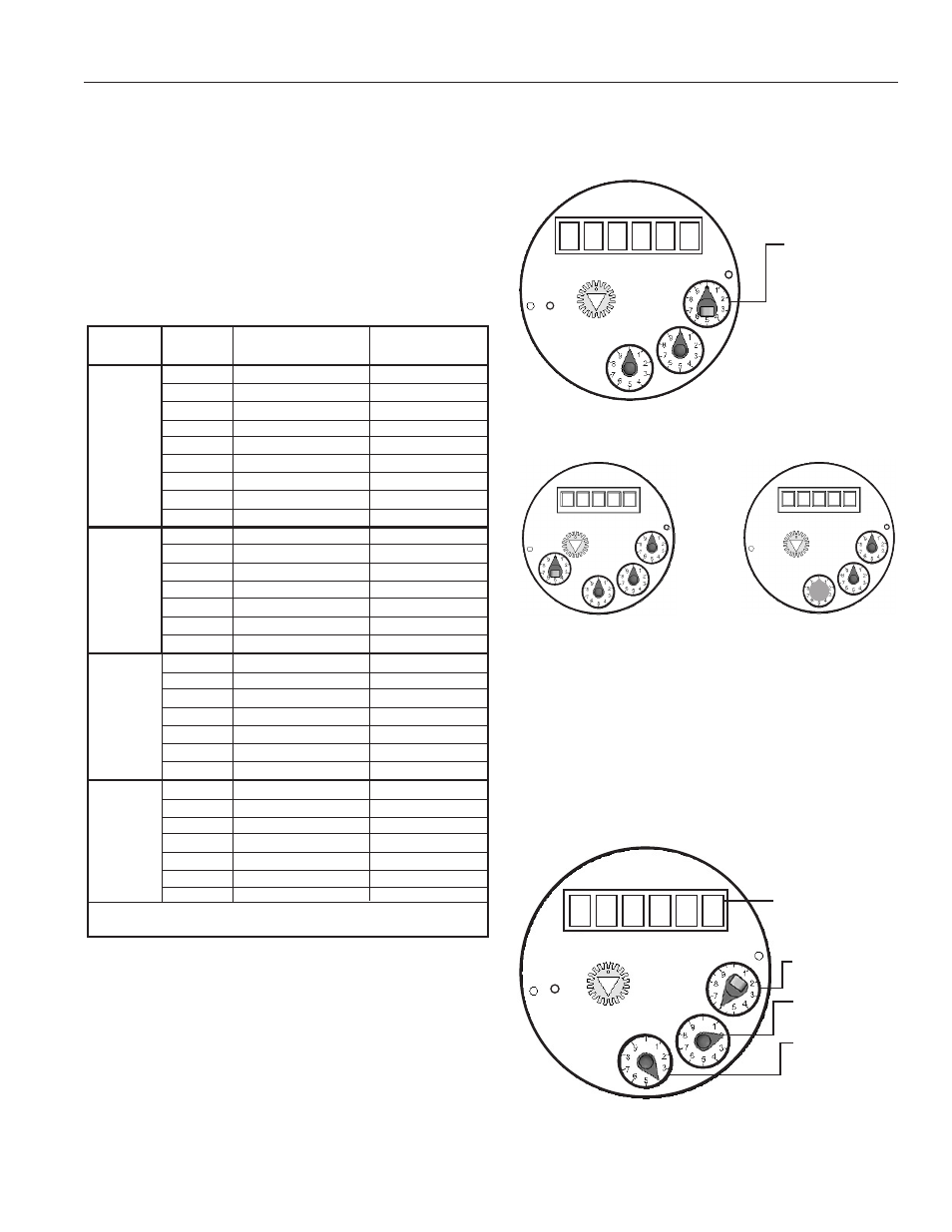
Sample Set-Up.
A 1” meter is shown with the magnet
pointer set at the x10 dial, with a pulse rate of 100 Gal-
lons per Pulse (that is, 10 increments on the x10 dial, or
10x10=100 Gal/Pulse).
x1 Gal Dial
(reads 2x1)
x0.1 Gal Dial
(reads 4x0.1)
Six-Digit Totalizer
(reads 138x100)
X10
Reading Your Meter.
The Total Flow that has passed
through your meter is read by starting at the top of the reg-
ister with the Six-Digit Totalizer, and then reading clockwise
around the small dials. In the example below, the Six-Digit
Totalizer reads 13,800 (138 x 100), and the dials read 60
(6 x 10), 2 (2 x 1), and .4 (4 x .1) respectively. The Total
Flow is 13,862.4 gallons.
U.S. GALLONS
25mm
40˚C
X100
X10
X1
X0.1
Col. 1
Col. 2
Col. 3
Col. 4
[With the magnet pointer
on the x1 dial, the pulse
rate would be 10x1=10
Gal/Pulse. With the mag-
net pointer on the x0.1 dial,
the pulse rate would be
10x.1=1 Gal/Pulse.]
Special Configurations.
The 3/4” meter has a fourth dial,
as shown above. The x0.01 dial is
used for 20 P/G and 10 P/G rates.
Note: The 3/4” meter has a 5 digit
totalizer.
The 4 P/G rate requires
a special magnet, placed
on the x0.1 dial, as shown
above.
(NOTE: Disregard the color of the numbers on the totalizer when reading
your total.)
The “ones” digit is significant but the fact that it is red is not significant.
1 3 8
X100