Pyromation Series 810 1_8 DIN User Manual
Page 2
Parameter
Legend
for 1 sec
followed
by
Set
Value
Adjustment Range &
Description
Default
Value
Units
Display
(
1
/
8
Din
Only )
Ww
Ww
Ww
Ww
Read/Write
Comms Write
Read only
Ww
Ww
Ww
Ww
Reset latched relay(s)
Initiate Tare (zero display)
Reset min/max PV values
Reset Alarm 1 elapsed time
Digital Input
Usage
Reset Alarm 1 elapsed time
& min/max PV values
Config Lock
####
Config Mode lock code, to
))))
))))
))))
))))
4. SETUP MODE
Note: Configuration must be completed before adjusting Setup parameters.
First select Setup mode from Select mode (refer to section 2). Press to scroll
through the parameters
(while this key is pressed, and for 1 sec after, the parameter
legend is shown, then the current value)
. Press or to change the value.
To exit from Setup mode, hold down and press to return to Select mode.
Note: Parameters displayed depends on how instrument has been configured.
Parameter
Legend
for 1 sec
followed
by
Set
Value
Adjustment Range &
Description
Default
Value
Units
Display
(
1
/
8
Din
Only )
Input Filter Time
Constant
OFF or 0.5 to 100.0 secs
.
Process Variable
Offset
±
Span of controller
.
Raw PV value
Linear input value, un-scaled (mA, mV or VDC)
blank
High Alarm 1
Max
Low Alarm 1
Alarm 1 value, adjustable within scaled
range, in display units
Min
(
Alm1
only = )
Alarm 1
Hysteresis
1 LSD to full span in display units on
safe side of alarm
High Alarm 2
Max
Low Alarm 2
Min
Al 2 Hysteresis
Options as for alarm 1
!!!!
High Alarm 3
Max
Low Alarm 3
Min
Al 3 Hysteresis
Options as for alarm 1
*
*
*
*
High Alarm 4
Max
Low Alarm 4
Min
Al 4 Hysteresis
Options as for alarm 1
High Alarm 5
Max
Low Alarm 5
Min
Al 5 Hysteresis
Options as for alarm 1
5
5
5
5
Scaling
Breakpoint 1
####
Multi-point scaling breakpoint 1 value,
adjustable from to
in % of span
Display Value 1
Value to be displayed at multi-point
scaling breakpoint 1, in display units
Range
Max
Scaling
Breakpoint 2
####
Multi-point scaling breakpoint 2, adjustable up to
100% of span. Must be >
####
value
Display Value 2
Value to be displayed at Multi-point scaling
breakpoint 2, in display units
Scaling
Breakpoint 3
####
Multi-point scaling breakpoint 3, adjustable up to
100% of span. Must be >
####
value
Display Value 3
Value to be displayed at Multi-point scaling
breakpoint 3, in display units
Scaling
Breakpoint 4
####
Multi-point scaling breakpoint 4, adjustable up to
100% of span. Must be >
####
value
Display Value 4
Value to be displayed at Multi-point scaling
breakpoint 4, in display units
Scaling
Breakpoint 5
####
Multi-point scaling breakpoint 5, adjustable up to
100% of span. Must be >
####
value
Display Value 5
Value to be displayed at Multi-point scaling
breakpoint 5, in display units
Scaling
Breakpoint 6
# %
# %
# %
# %
Multi-point scaling breakpoint 6, adjustable up to
100% of span. Must be >
####
value
Display Value 6
%%%%
Value to be displayed at Multi-point scaling
breakpoint 6, in display units
%%%%
Scaling
Breakpoint 7
# *
# *
# *
# *
Multi-point scaling breakpoint 7, adjustable up to
100% of span. Must be >
# %
# %
# %
# %
value
Display Value 7
*
**
*
Value to be displayed at Multi-point scaling
breakpoint 7, in display units
*
**
*
Scaling
Breakpoint 8
# (
# (
# (
# (
Multi-point scaling breakpoint 8, adjustable up to
100% of span. Must be >
# *
# *
# *
# *
value
Display Value 8
(
((
(
Value to be displayed at Multi-point scaling
breakpoint 8, in display units
(
((
(
Scaling
Breakpoint 9
#### )
))
)
Multi-point scaling breakpoint 9, adjustable up to
100% of span. Must be >
# (
# (
# (
# (
value
Display Value 9
)
))
)
Value to be displayed at Multi-point scaling
breakpoint 9, in display units
)
))
)
Tare Feature
Enables or disables the input
auto-zero Tare feature
Setup Lock Code
####
to
))))
))))
))))
))))
Note: Operator mode screens follow, without exiting from Setup mode.
5. MESSAGES & ERROR INDICATIONS
These messages indicate that the instrument may require attention, or there is a
problem with the signal input connection.
The message legend is shown for 1
second, followed by its value.
Caution:
Do not continue with the process until the issue is resolved.
Parameter
Legend
for 1 sec
followed
by
Value Description
Units
Display
(
1
/
8
Din
Only )
Instrument
parameters are in
default conditions
Configuration & Setup is required.
This screen is seen at first turn on,
or if hardware configuration is
changed. Press to enter
Configuration Mode, next press
or to enter the unlock code,
then press to proceed
Input Over Range
++++
,
,,
,
Input signal is > 5% over-range
Input Under Range
++++ ,
,,
,
Input signal is > 5% under-range
(>10% under-range for 4 to 20mA,
1 to 5V and 2 to 10V
ranges)
Input Sensor Break
-
-
-
-
Break detected in input signal
sensor or wiring
Option 1 Error
..
..
..
..
Option 1 module fault
Option 2 Error
..
..
..
..
Option 2 module fault
Option 3 Error
..
..
..
..
Option 3 module fault
Option A Error
..
..
..
..
Option A module fault
Option B Error
..
..
..
..
..
..
..
..
Shown if any module is fitted
(option B not used on Indicators)
Note:
++++
,
,,
,
,
++++ ,
,,
,
or
-
-
-
-
may also be displayed if an incorrect input type is
selected.
6. OPERATOR MODE
This mode is entered at power on, or accessed from Select mode (see section 2).
Note: All Configuration mode and Setup mode parameters must be set as
required before starting normal operations.
Press to scroll through the parameters
(while this key is pressed, and for 1 sec
after, the parameter legend is shown, followed by the current value)
.
Note: All Operator Mode parameters in Display strategy 6 are read only (see
in configuration mode), they can only be adjusted via Setup mode.
Legend
for 1 sec
followed
by
Value Display Strategy and
When Visible
Description
Units
Display
(
1
/
8
Din
Only )
####
PV
Value*
Always
Process Variable value
Read only
Latched outputs can be reset
°
,
°
or
blank
Mm
Mm
Mm
Mm
Max PV
Value Strategies , , , , &
%%%%
Maximum displayed value
(inc
++++
,
,,
,
or
-
-
-
-
)
since
Mm
Mm
Mm
Mm
last reset.
To reset, press or for
3 seconds,
display =
&&&&
when reset
°
,
°
or
blank
Mm
Mm
Mm
Mm
Min PV
Value Strategies , , , , &
%%%%
Minimum displayed value
(inc
++++ ,
,,
,
or
-
-
-
-
)
since
Mm
Mm
Mm
Mm
last reset.
To reset, press or for
3 seconds,
display =
&&&&
when reset
°
,
°
or
blank
Elapsed
Time
Strategies , &
%%%%
if alarm 1 configured.
Format mm.ss to 99.59
then mmm.s
(10 sec increments)
Shows
++++
,
,,
,
if >999.9
Accumulated alarm 1 active
time since
last reset.
To reset, press or for
3 seconds,
display =
&&&&
when reset
Alarm 1
Value
Strategies , , &
%%%%
if alarm 1 configured
Alarm 1 value, adjustable
except in Strategy 6
(
Alm1
only = )
Alarm 2
Value
Strategies , , &
%%%%
if alarm 2 configured
Alarm 2 value, adjustable
except in Strategy 6
Alarm 3
Value
Strategies , , &
%%%%
if alarm 3 configured
Alarm 3 value, adjustable
except in Strategy 6
Alarm 4
Value
Strategies , , &
%%%%
if alarm 4 configured
Alarm 4 value, adjustable
except in Strategy 6
Alarm 5
Value
Strategies , , &
%%%%
if alarm 5 configured
Alarm 5 value, adjustable
except in Strategy 6
Active
Alarm
Status*
When one or more
alarms are active
L
Alarm 4 active
Alarm 2 active
Alarm 3 active
Alarm 5 active
Latched outputs can be reset
if
alarm 1
active
Alarm Indication
The Active Alarm Status screen indicates any active alarms. In addition, the
associated Alarm LED flashes.
For latching alarm outputs, the LED flashes when the alarm condition exists,
and goes to ON when the alarm condition is no longer present if the output has not
yet been reset.
*Resetting Latched Alarm Outputs
Any latched outputs can be reset whilst the Process variable or Alarm Status
screens are displayed, by pressing the or key, via the Digital Input (if fitted)
or with a communications command via the RS485 module (if fitted).
Note: Outputs will only reset if their alarm condition is no longer present.
Caution:
A reset will affect ALL latched outputs.
Additional
1
/
8
Din Indicator Units Display and LED’s
In Operator Mode, a Units display shows
°
or
°
when temperature values are
shown. This display is also used in other modes as a confirmation of the parameter
type currently shown in the main display. The SET LED indicator is off in
Operator Mode, Flashing in Configuration Mode and ON in Set-up mode.
MIN and MAX LED’s light when these stored values are shown.
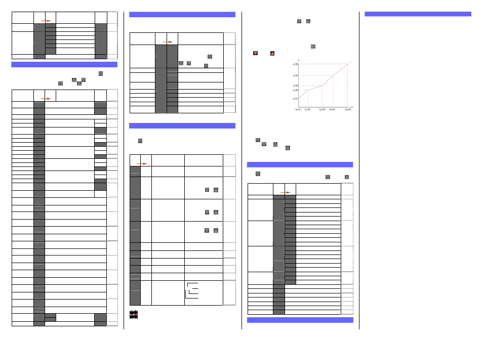
Multi-Point Scaling
When enabled (
Mm
Mm
Mm
Mm
=
),
up to 9 breakpoints can be set to
compensate for non-linear input
signals.
For each breakpoint, the input
scale value (
####
n) is entered
in % of input span, followed by
the value to be shown (
n)
in display units.
Each breakpoint’s input scale
value must be higher than the
previous value, but the display
values can be higher or lower.
Any scale value set to 100%
becomes the last in the series.
Tare Feature
When Tare is enabled (
=
), it can be used to set the displayed value to
zero automatically, by making the PV Offset parameter equal, but opposite to, the
current process variable value. Tare can be initiated via the Digital Input (if fitted),
with a communications command via the RS485 module (if fitted) or by using the
following key press sequence:
Press until the process variable is displayed.
Hold down and together for three seconds until the display shows
/ $
/ $
/ $
/ $????
Release both keys and press within 3 seconds to confirm the request.
The display should read briefly, then begin responding to input signal changes.
Note: Tare request is aborted if this sequence is not followed exactly.
7. PRODUCT INFORMATION MODE
First select Product information mode from Select mode (refer to section 2).
Press to view each parameter
(while this key is pressed, and for 1 sec after, the
parameter legend is shown, followed by its value)
. Hold down and press to
return to Select mode. Note: These parameters are all read only.
Parameter
Legend
for 1 sec
followed
by
Value Description
Units
Display
(
1
/
8
Din
Only )
Input type
'
'
'
'
Universal input
No option fitted
/
/
/
/
Relay output
SSR drive output
Triac output
Option 1 module
type fitted
Linear DC voltage / current output
No option fitted
/
/
/
/
Relay output
/
/
/
/
Dual Relay (outputs 2 & 4)
SSR drive output
Triac output
Option 2 module
type fitted
Linear DC voltage / current output
No option fitted
/
/
/
/
Relay output
/
/
/
/
Dual Relay (outputs 3 & 5)
SSR drive output
Linear DC voltage / current output
Option 3 module
type fitted
####
24V DC Transmitter power supply
No option fitted
(
((
(
RS485 communications
Auxiliary Option A
module type fitted
Digital Input
Firmware type
01
01
01
01
Value displayed is firmware type number
Firmware issue
'$$
'$$
'$$
'$$
Value displayed is firmware issue number
Product Rev Level
.
.
.
.
Value displayed is Product Revision Level
Manufactured Date
Mm
Mm
Mm
Mm
Month & year of manufacture. Format mmyy
Serial number 1
First four digits of serial number
Serial number 2
Middle four digits of serial number
Serial number 3
Last four digits of serial number
####
8. SERIAL COMMUNICATIONS
Refer to the full user guide (available from your supplier) for details.
9. SPECIFICATIONS
UNIVERSAL INPUT
Thermocouple
Calibration:
±
0.1% of full range,
±
1LSD (
±
1°C for Thermocouple CJC).
BS4937, NBS125 & IEC584.
PT100 Calibration:
±
0.1% of full range,
±
1LSD.
BS1904 & DIN43760 (0.00385
Ω
/
Ω
/°C).
DC Calibration:
±
0.1% of full range,
±
1LSD.
Sampling Rate:
4 per second.
Impedance:
>10M
Ω
resistive, except DC mA (5
Ω
) and V (47k
Ω
).
Sensor Break
Detection:
Thermocouple, RTD, 4 to 20 mA, 2 to 10V and 1 to 5V ranges
only. High alarms activate for thermocouple/RTD sensor break,
low alarms activate for mA/V DC sensor break.
Isolation:
Isolated from all outputs (except SSR driver).
Universal input must not be connected to operator accessible
circuits if single relay outputs are connected to a hazardous
voltage source. Supplementary insulation or input grounding
would then be required.
DIGITAL INPUT
Voltage Input:
Volt-free Contacts:
Reset or Tare occurs on high (2 to 24VDC) to low <0.8VDC, or
Open to Closed transition.
Isolation:
Reinforced safety isolation from inputs and other outputs.
OUTPUTS
Relay
Contact Type &
Rating:
Single pole double throw (SPDT), latching or non-latching
action (selectable); 2A resistive at 120/240VAC.
Lifetime:
>500,000 operations at rated voltage/current.
Isolation:
Basic Isolation from universal input and SSR outputs.
Dual Relay
Contact Type &
Rating:
Single pole single throw (SPST), latching or non-latching
action (selectable); 2A resistive at 120/240VAC.
Lifetime:
>200,000 operations at rated voltage/current.
Isolation:
Reinforced safety isolation from inputs and other outputs.
SSR Driver
Drive Capability:
SSR drive voltage >10V into 500
Ω
min.
Isolation:
Not isolated from universal input or other SSR driver outputs.
Triac
Operating Voltage: 20 to 280Vrms (47 to 63Hz).
Current Rating:
0.01 to 1A (full cycle rms on-state @ 25°C);
derates linearly above 40°C to 0.5A @ 80°C.
Isolation:
Reinforced safety isolation from inputs and other outputs.
Linear DC
Accuracy:
±
0.25% (mA @ 250 , V @ 2k ). Degrades linearly to
±
0.5%
for increasing burden (to specification limits).
Resolution:
8 bits in 250mS (10 bits in 1s typical, >10 bits in >1s typical).
Isolation:
Reinforced safety isolation from inputs and other outputs.
Transmitter PSU
Power Rating:
24V TxPSU Module; Unregulated 20 to 28V DC into 910
Ω
min
Linear output Module; Regulated 0.0 to 10.0V into 500
Ω
min.
Isolation:
Reinforced safety isolation from inputs and other outputs.
SERIAL COMMUNICATIONS
Physical:
RS485, at 1200, 2400, 4800, 9600 or 19200 bps.
Protocols:
Selectable between Modbus and West ASCII.
Isolation:
Reinforced safety isolation from all inputs and outputs.
OPERATING CONDITIONS (FOR INDOOR USE)
Ambient
Temperature:
0°C to 55°C (Operating), –20°C to 80°C (Storage).
Relative Humidity: 20% to 95% non-condensing.
Supply Voltage and
Power:
100 to 240VAC
±
10%, 50/60Hz, 7.5VA
(for mains powered versions), or
20 to 48VAC 50/60Hz 7.5VA or 22 to 65VDC 5W
(for low voltage versions).
ENVIRONMENTAL
Standards:
CE, UL & ULC
EMI:
Complies with EN61326 (Susceptibility & Emissions).
Safety
Considerations:
Complies with EN61010-1 & UL3121.
Pollution Degree 2, Installation Category II.
Front Panel Sealing: To IP66 (IP20 behind the panel).
PHYSICAL
Front Bezel Size:
1
/
16
Din = 48 x 48mm,
1
/
8
Din = 96 x 48mm
Depth Behind Panel:
1
/
16
Din = 110mm,
1
/
8
Din = 100mm.
Weight:
0.21kg maximum.
PV Input Signal
% of Span
D
is
pl
ay
ed
V
al
ue