Precision Control Systems PanelIR 4555 User Manual
Page 15
Model 4555 PanelIR
TM
User Manual
Installation
ELECTRICAL
INSTALLATION
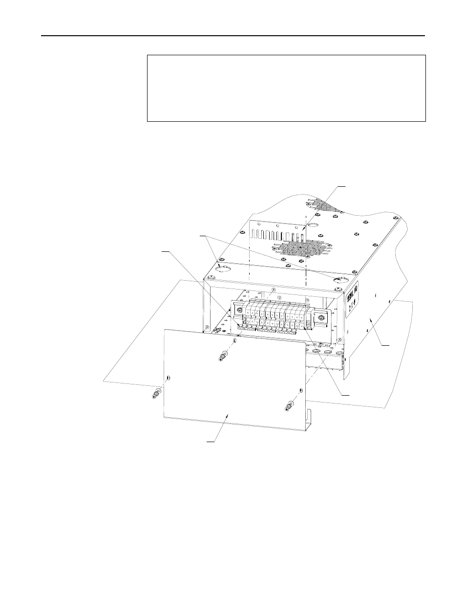
Figure 3-2 Terminal Strip
and Bus Bar
CAUTION!
All internal wiring of the model 4555 Panel IR should be high
temperature insulated wire as specified below or of an equivalent type:
• Lead wire type PFAH or TFE, 600V Maximum, 250°C maximum, UL
listed.
• Ampacity based on National Electrical Code Table 310.
As shown in Figure 3-2, the Model 4555 contains two electrical terminal blocks, one
each mounted on the internal heater housing, under each heater end cover. These
terminal blocks each contain contact points for electrical connection of each lamp of the
heater. In addition, each terminal strip contains a “bus bar” that provides electrical
connection between all contact points on the terminal block (Figure 3-2).
Electrical
"Knock-Outs"
Bus Bar
Heater
Housing
End Cover (2X)
Terminal Blocks
Jumper Bars (6X)
The presence of the bus and jumper bars on each terminal block allows the heater to be
easily wired in different configurations. A model 4555 heater wired in a single-zone
configuration is shown in Figure 3-3. In this configuration the lamps mounted in the
Model 4555 all simultaneously receive the same voltage from the power source. In this
case, electrical connection from each terminal block to the power source is made by a
single, high temperature grade, electrical wire as follows:
Research, Inc.
12