NSi Industries PC20A User Manual
Tork occupancy sensors, Passive infrared occupancy sensors ceiling mount, Occup ancy sensors
OCCUP
ANCY
SENSORS
TORK OCCUPANCY SENSORS
TORK
1 Grove St., Mt. Vernon, NY 10550 • Tel: 914-664-3542 • Fax: 914-664-5052 • Internet: http://www.tork.com
PASSIVE INFRARED
OCCUPANCY SENSORS
CEILING MOUNT
Three Versions for Open Areas,
Hallways, or W ide Area Coverage
APPLICATIONS
Controls:
• Fluorescent and Incandescent Lighting Systems
• HVAC Electrical Equipment
• Ventilating and Exhaust Fans
• Self-Contained Air Conditioning Units
For use in:
• Offices
• Motels
• Lavatories
• Conference Rooms
• Classrooms
• Hallways
FEATURES
Adjustable timer for delayed turn-off in 30 seconds to 15
minutes after no movement or presence is detected.
Manual override ON by inserting key in slot of unit (for
emergency use).
Powerpack (to be ordered separately)
is
capable of
operating up to four PC10A/PC10H/PC20A sensors.
SPECIFICA
TIONS
SENSOR MODEL #PC10A/PC10H/PC20A
Input Voltage: 24VDC (supplied by TRP). Input voltage
for TRP to be specified. 16 MA nominal.
View Angle: (Model PC10A/PC20A) 360°
Detection Range: (Model PC10H) 80’
Wiring: Class 2, #22 AWG (between sensor and powerpack)
Temperature Range: 0° to 150°F (–18°
to 66°C)
Size: 4-3/4” length x 2-13/16” width x 1-1/8” depth.
Weight: 3 oz.
Color: White
Mounting: Ceiling
For area coverage diagrams, see pages 72-73
MODEL #TRP POWERPACKS - MUST BE USED IN
CONJUNCTION WITH SENSOR
FOR CONTACT RATINGS, SEE PAGE 68
SPECIFICA
TION WRITER’S GUIDE
Furnish and install where indicated a passive infrared occupancy sensor
capable of (Model PC10A) covering an area of up to 1000 square feet or .
. .
(Model PC10H) for aisles, corridors, hallways with a detection range of 80
feet long x 16 feet wide . . . or (Model PC20A) covering an area of up of
2000 sq. ft. Sensor shall be equipped with a separate adjustment for
delayed time off of 30 seconds to 15 minutes. Sensor shall be designed for
mounting onto a ceiling.
Sensor is to be supplied with a transformer relay power pack which can be
installed remote from sensor using low voltage wire. (Powerpack can be
installed close to load in order to minimize line voltage wiring). The remote
powerpack shall be capable of installation in a single or multiple gang box.
One remote powerpack shall be capable of operating a maximum of four
sensors. Sensor and transformer relay powerpack shall be TORK Models
PC10A/PC10H/PC20A and TRP respectively.
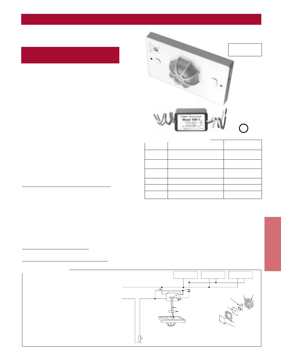
MODEL
DESCRIPTION
INPUT VOLTAGE
PC10A
Sensor only
24 VDC supplied
from powerpack
PC10H
Sensor only – for hallways
24 VDC supplied
from powerpack
PC20A
Sensor only – for wide
24 VDC supplied
area coverage
from powerpack
TRP1
Powerpack
120 VAC
TRP2
Powerpack
277 VAC
TRP5
Powerpack
230 VAC
ORDERING INFORMATION
BALLAST
LIGHT FIXTURE #1
BALLAST
LIGHT FIXTURE #2
BALLAST
LIGHT FIXTURE #3
120 VAC OR 277 VAC
NEUTRAL
WHITE
RED
BLACK
(LINE)
HOT
BLACK
RED
BLUE
POWER PACK
MODEL TRP1 120 VAC
20 AMP 2400 WATTS
EXISTING SWITCH CAN REMAIN
IN RETROFIT INSTALLATIONS.
IT IS NOT REQUIRED IN NEW
CONSTRUCTION UNLESS MANUAL
OFF IS DESIRED IN WHICH CASE
SIMPLY RUN 22AWG WIRE FROM
TRP AND BREAK THE BLUE WIRE.
POWER PACK
MODEL TRP2 277 VAC
20 AMP 4800 WATTS
POWER PACK
MOUNT IN APPROVED
JUNCTION BOX OR
BALLAST HOUSING OF
FIRST LIGHT FIXTURE
LOAD
RED
LOW VOLTAGE CABLE
3 CONDUCTOR 22 GA.
CLASS 2 WIRING
Power Pack 277V
Model TRP2
or Power Pack 120V
Model TRP1
New Cover With
1/2 K.O. Provision
New
Extension
Box
Existing
Junction
Box
Bend Tabs After
Inserting in K.O.
Hole
New Extension Box
Only Used When
Low Voltage Wiring
Has to be Enclosed
SPECIAL NOTES: One Power Pack can operate 4 PC10/PC10H
Units and all low voltage wires are connected in parallel. Some
existing lighting systems are wired directly from Breaker Control
Cabinet and therefore have no light switches. For this type of
lighting system, it is sometimes more convenient to install Power
Packs close to the Circuit Breaker Control Cabinet. This allows for
OPTIONAL MANUAL
ON OVERRIDE
SWITCH
PC10A/20A SERIES
Standard low voltage installation
with remote power pack
in accessible tile ceiling
SPECIAL NOTES: One Power Pack can operate 4 sensors and all
low voltage wires are connected in parallel. Some existing lighting
systems are wired directly from Breaker Control Cabinet and there-
fore have no light switches. For this type of lighting system, it is
sometimes more convenient to install Power Packs close to the
Circuit Breaker Control Cabinet. This allows for ease of circuit identi-
fication, and also wiring of low voltage cable to sensor units.
TRPS are UL Listed.
Meets California
Energy Commission
Title 24 requirements.
PC10A/20A SERIES
Model TRP1
Model PC10A
LISTED
UL
®
PC10A Covers up to 1000 square feet
PC20A Covers up to 2000 square feet
PC10H Covers up to 40 feet X 16 feet