E501t, On interval timer, Installation & wiring instructions – NSi Industries E501T User Manual
Page 3: Caution
MODEL#:
E501T
The E501T is designed for interval timing for a variety of applications. This timer is user adjustable with interval durations ranging from ten (10) seconds minimum to 12 hours
maximum. Continuous ON and continuous OFF settings are included.
Timing selection is made by setting a rotary dial, which contains 32 precisely defined positions. The timing selection may be started (or stopped) from the STOP/START button on the
face of the timer or from a remote momentary switch. If a maintained switch closure is used for the remote input, the button on the face can be disabled.
POwEr
rEquirEMEnts:
Inputs: 120 and 240 VAC (+10% -15% at 60 Hz)
Outputs: SPDT relay with 20 Amp N.O. and 10 Amp N.C. general purpose at 120,240 VAC; N.O. 1 HP at 120 VAC, 2HP at 240 VAC
EnvirOnMEntaL: Operating Temperature Range: 32°F to 122°F (0°C to 50°C). Operating Humidity Range: Relative humidity up to 100%
Water Resistance: The control will be capable of direct low-pressure water wash down according to NEMA 4X specification.
COntaCt
ratinG:
EnCLOsurE:
NEMA type 4X (indoor use only) enclosure standard (E501T). Watertight cover with gasket is flame retardant UV stabilized and non-metallic. In grey.
MOuntinG:
Control is compatible for mounting to Tork’s NEMA 4X nonmetallic enclosure
DiaLs:
Sealed from external access
MaintEnanCE:
Cleaning: Use only mild detergent and water
to dean the enclosure
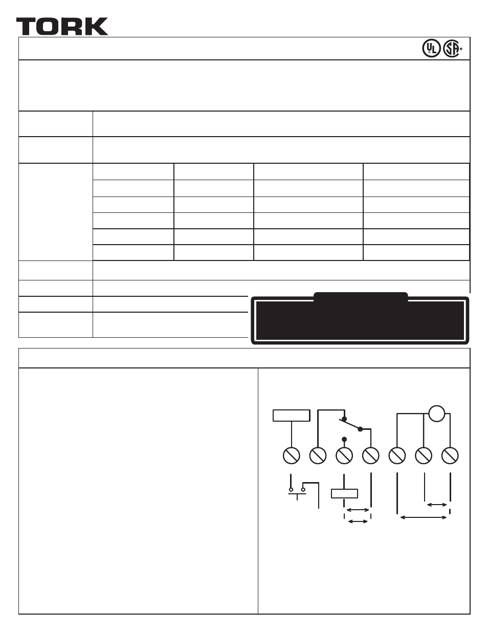
INSTALLATION & WIRING INSTRUCTIONS
Note:
Wiring connections are made to a six-position: terminal block.
All terminals accept AWG #18 to AWG #12 wire.
1. Turn off all power to the timer circuit at the distribution panel before
beginning the installation.
2. The E501T box contains knockouts on two sides. Determine the most
convenient way to mount the box to the conduit and remove the
appropriate knockout. To secure the box to a fixed location, use at
least two of the four box mounting knockouts located on the back of
the box.
3. Wire timer for either 120 VAC or 240 VAC as shown by the wiring
diagram. Wire the load to the timer as shown in the wiring diagram,
noting the contact load type and ratings shown.
4. Connect optional trigger contacts to the timer as shown in the wiring
diagram.
5. Securely attach the timer to Tork’s NEMA 4X (for indoor use only)
non-metallic enclosure with the included screws.
®
ON INTERVAL TIMER
VOLTAGE
LOAD TYPE
N.O. CONTACTS
N.C. CONTACTS
120-240 VAC
Resistive
20 A
10 A
120-240 VAC
General Purpose
20 A
10 A
120 VAC
Motor
1 HP
¼ HP
208-240 VAC
Motor
2 HP
½ HP
120-240 VAC
Pilot Duty
470 VA
275 VA
TRIGGER
T
LOAD
START
NC
NO
COM
240V/L1
120V NEUT/L2
120V
L
N
FOR 240V
L2
L1
EXTERNAL
TRIGGER
(CONTACTS)
SPDT
120V
L
N
L1
L2
FOR 240V
APPLY ONLY ONE VOLTAGE
FOR 120V
(L)
FOR 240V
(L1)
! CAUTION !
RISK OF ELECTRIC ShOCK
Disconnect power at main panel prior to installing
or servicing this lighting control or the equipment connected to it.