Tork, Digital time switch, Wiring diagrams – NSi Industries ES103A User Manual
Page 2: Warning, Specifications
TORK
DIGITAL TIME SWITCH
SPECIAL ENCLOSURE: -C -Y -FLG -O
TO SET CLOCK
Press MODE key until display shows CLK.
Press DAY key to select current day. Press HOUR key to select current hour.
Check A (AM) or P (PM). Press MIN key to select current minute. Press ENTER
key and the clock is set for current time and day.
TO SET SCHEDULE
If display does not show SCH, press mode key until display shows SCH.
Note: There are 7 ON and 7 OFF set points which alternate (set point #1 is ON;
#2 is OFF; #3 is ON).
The display will Indicate it is ready to receive SCH setpoint #1 which is an ON
event.
Press HOUR and MIN keys for the first ON setting (check for AM or PM).
Press ENTER key to store the information and display will indicate it is ready to
receive SCH setpoint #2 which is an OFF event.
Press HOUR and MIN keys for the first OFF setting. Then press ENTER key to
store the information and display will indicate it is ready to receive SCH set-
point #3 which is the next ON event.
Proceed for up to 7 ON and 7 OFF setpoints. Then press MODE key and unit
will go to the AUTO (run) mode.
In the AUTO mode, the unit will display current time and day as well as load sta-
tus (ON and OFF).
Note: When the unit is returned to the auto mode, check the load status of the current set-
ting. If it is showing OFF but should be ON, press the override key. The unit will correct itself
at the next scheduled event and no further alteration will be necessary.
TO SET SKIP DAYS
Press MODE key until display shows SKIP. Press DAY key and M (Monday)
starts flashing. Press SKIP key to set or delete a flashing day. Press DAY key to
advance the days. When all desired skip days are selected (showing solid on
LCD), press ENTER key.
Note: During skip days, only OFF events are executed. This will allow the load to turn off if it
was overridden ON during these days.
REVIEW/MODIFY
1. CLOCK - ALTER TIME. Press mode key until display shows CLK. Press
DAY, HOUR, and MIN keys to change to the correct time. Press ENTER.
2. SCHEDULE - REVIEW. Press mode key until display shows SCH. Press
ENTER key repeatedly to review all the scheduled entries. During the review,
any selected skip days will appear on the display with the word SKIP.
3. SCHEDULE - MODIFY. During the review (see previous section) any set-
point can be modified or deleted. Use the HOUR and MIN keys to modify.
Use the DELETE key to eliminate that event. Press ENTER key after each
modification.
4. SKIP DAYS - ADD/DELETE. Press MODE key until display shows SKIP. All
previously selected skip days will appear. To add or delete days, follow steps in
section titled “TO SET SKIP DAYS”.
OVERRIDE - TEMPORARY
In order to temporarily change the current ON or OFF status of a load, simply
press the override key when the unit is in the AUTO mode. The altered load sta-
tus will flash. Override is in effect until the next scheduled event. In order to can-
cel the override, press override key again.
OVERRIDE - LONG TERM
Press mode key until display shows MAN (manual). Normal schedule will not
be executed and the load status will remain unchanged as indicated. Press
the OVERRIDE key to obtain the correct status or to alter the load status.
®
UL
469D
LISTED
®
LR21743
MLI-162(B)
1 GROVE STREET, MT. VERNON, NY 10550 TEL: 914-664-3542
FAX: 914-664-5052
3
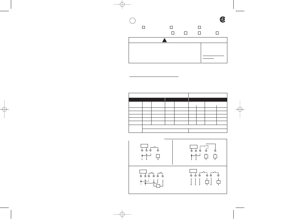
SPST
4
LOAD
120/277VAC
E101A
E120A
1
2
N
L
N
TIMER
SUPPLY
TIMER
SUPPLY
120/277VAC
3
4
5
SPDT
1
2
L
N
LOAD
LOAD
N
N
E103A
3
DPST
4
LOAD
208 OR 240VAC
1
2
L1
L2
TIMER
SUPPLY
6
5
DPST
TIMER
SUPPLY
3
5
6
120/277VAC
SINGLE PHASE
4
L1
L1
L1
N
1
2
LOAD
N
LOAD
N
WIRING DIAGRAMS
ES101A ES120A ES103A
ES101A
ES103A
ES120A
WARNING
!
Lockout power at main panel before initial wiring or servicing
of this time switch and any equipment connected to it. More
than one disconnect point may be required. Install and use in
accordance with national and local electrical codes. Use cop-
per wire AWG #8-16 suitable for 75°C (167°F). Metal enclo-
sure must be properly grounded.
Insulator must be
replaced below before
turning on electricity.
Inform electrician if it
is missing.
SPECIFICATIONS
Input Voltage: 120/208 - 277VAC, 50/60Hz. (Jumper selectable), 4VA max.
User Selectable by Jumper Setting:
See caution on front page regarding
clock voltage selection and circle your input voltage below.
120V 208-277V
Dry Contact Ratings:
SERIES E101A (SPST) AND E103A (DPST)
SERIES E120A (SPDT)
TYPE
208-277
208-277
120VAC
208-277VAC
OF LOAD
120VAC
VAC
120VAC
VAC
N.O.
N.C.
N.O.
N.C.
Resistive
40A
40A
30A
30A
30A
30A
30A
30A
Inductive
40A
40A
30A
30A
30A
30A
30A
30A
Ballast
30A
20A
30A
20A
30A
10A
20A
10A
Tungsten
10A
–
10A
–
10A
2A
–
–
Pilot Duty
720VA
720VA
720VA
720VA
720VA 720VA
720VA
720VA
Motor
1 HP @ 120V; 1-1/2 HP @ 208V; 2 HP @ 240-277V
30A resistive @ 28 VDC
NO/NC 30A resistive @ 28 VDC
UL
CSA
UL and CSA
ES SERIES INSTRUCTIONS2003 11/18/03 5:01 PM Page 1