Pin functions, Safety various operating modes – Martel Electronics DPM950 User Manual
Page 2
PIN FUNCTIONS
1. LP-
Negative power supply to LED backlighting.
2. LP+
Positive power supply to LED backlighting.
3. V-
Negative power supply connection.
4. V+
Positive power supply connection.
5. -5V
Output from negative rail generator circuit. This output is an inversion of V+ (DPM 950S only).
6. TEST
Connect to V+ to display all segments except DPs. It should not be operated for more than a few seconds as the D.C. voltage applied to
the LCD may 'burn' the display. This pin is normally at 5V below V+ and is the ground for the digital section of the meter. It can be
used to power external logic up to a maximum of 1mA.
7. IN LO
Negative measuring differential input. Analogue inputs must be no closer than 1V to either positive or negative supply. The negative
8. IN HI
Positive measuring differential input.
supply of the DPM 950S is generated internally and mirrors the positive supply voltage.
9. COM
Ground for the analogue section of the A/D converter, it is actively held at approximately 2.8V below V+ and must not be allowed to
sink excessive current (>100 A) by, for instance, connecting to a higher voltage.
11. REF LO
Negative input for reference voltage. Can be connected to COM via link 3.
12. REF HI
Positive input for reference voltage. Connected via link 1 to internal reference.
13. XDP
Annunciator Drive Waveform, this is an inversion of the backplane.
14. DP1
199.9
15. DP2
19.99
Connect to V+ to display required Decimal Point or short corresponding DP link.
16. DP3
1.999
18 & 32. BP
LCD backplane drive waveform.
23. REF-
Negative output from internal reference.
24. REF+
Positive output from internal reference.
25. LO BAT
Used to control the low battery annunciator externally, cut link 12 and take to V+ to turn on annunciator.
The annunciator turn on point can also be set by adjusting the BAT potentiometer (R10), in which case do
not connect to this pin and leave link 12 intact.
26. REF BG
Output from internal bandgap reference. (Factory fitted option.)
27.
Alarm annunciator, cut link ALM and take to XDP to display.
28. :
Colon annunciator, cut link COL and take to XDP to display.
29. -
Polarity annunciator, connected via link 11 to polarity output of IC1. Cut link 11 and either take to XDP to
display or make other side of link 11 to hold off.
30. POL
Polarity output of IC1.
31. CLK
May be used to override the internal oscillator and control the sample rate. Link 14 must then be made.
µ
To comply with the Low Voltage Directive (LVD 93/68/EEC), input voltages to the module’s pins must not exceed 60Vdc. If voltages to the measuring
inputs do exceed 60Vdc, then fit scaling resistors externally to the module. The user must ensure that the incorporation of the DPM into the user’s
equipment conforms to the relevant sections of BS EN 61010 (Safety Requirements for Electrical Equipment for Measuring, Control and Laboratory Use).
SAFETY
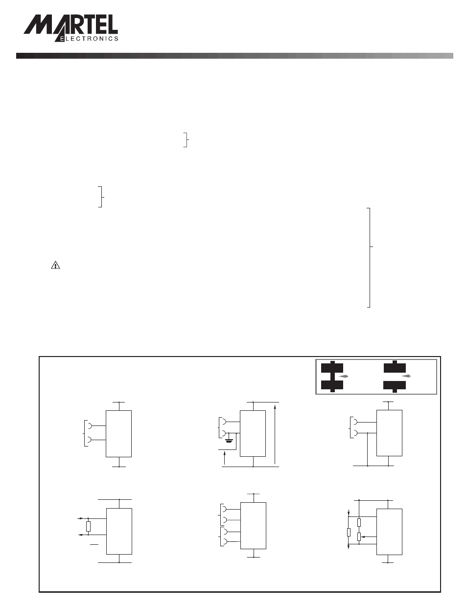
VARIOUS OPERATING MODES
ON-BOARD LINKS: In order to quickly and easily change operating modes for different applications,
the meter has several on-board links. They are designed to be easily opened (cut) or shorted (soldered).
Do not connect more than one meter to the same power supply if the meters cannot use the same
signal ground. Taking any input beyond the power supply rails will damage the meter.
Normally
SHORTED
Cut to
OPEN
Normally
OPEN
Solder to
SHORT
Measuring a floating voltage source
of 200mV full scale.
Measuring current. Supply MUST
be isolated.
Split rail supply (DPM 950)
Measuring 4-20mA to read 0-999
(supply MUST be isolated).
Measuring a single ended input
referenced to supply (DPM 950S).
Measuring the ratio of two voltages.
Reading = 1000 V /V
50mV <
<200mV
1
2
V
V < 2V
2
1
2.
Check Links 2 & 3 are SHORTED.
Check Links 2 & 3 are SHORTED.
Check Links 1 & 4 are OPEN.
Check Link 3 is SHORTED.
V+
V+
V+
V+
4
7
8
IN HI
IN HI
IN LO
IN LO
R= 0.2
I
FSR
3
3
R
7
8
4
V-
V-
V-
V-
+
-
±200mV
±200mV
7
+
+
-
-
V
2
V
1
8
REF HI
IN HI
IN LO
REF LO
4
11
3
V-
V-
12
V+
V+
7
8
V-
V-
V+
V+
4
3
+
-
IN
HI
IN
LO
Check Link 3 is SHORTED.
Check Link 3 is SHORTED.
IN
HI
IN
LO
COM
I
OUT
I
IN
V-
V-
V+
V+
9
7
8
3
4
220k
5k
Set
Zero
6R2
V+
V+
4
7
8
IN HI
14V max
7V min
IN LO
±200mV
3
V-
V-
0V
1V min
+
-
Specifications liable to change without prior warning
DPM 950
Issue 8
August/2002
M.C.
Applies to DPM 950/4
Only Pins 1-16 are fitted,
these functions are
available but a connector
is not provided.
LASCAR ELECTRONICS LTD.
MODULE HOUSE, WHITEPARISH,
WILTSHIRE SP5 2SJ UK
TEL: +44 (0)1794 884567 FAX: +44 (0)1794 884616
E-mail: [email protected]
LASCAR ELECTRONICS (HK) LIMITED
FLAT C, 5/FL., LUCKY FTY. bldg., 63-65 HUNG TO ROAD
KWUN TONG, KOWLOON, HONG KONG
TEL: +852 2797 3219
FAX: +852 2343 6187
E-mail: [email protected]
LASCAR ELECTRONICS INC.
3750 West 26th Street,
Erie, PA 16506 USA
TEL: +1 (814) 835 0621 FAX: +1 (814) 838 8141
E-mail: [email protected]
PO Box 770, Londonderry, NH 03053 1-800-821-0023
www.martelcorp.com