Dpm 1as-bl, Applications, Scaling – Martel Electronics DPM 1AS-BL User Manual
Page 4: 3½ digit backlit lcd voltmeter module, 5v supply operation, 9v supply operation
DPM 1AS-BL
3½ Digit Backlit LCD Voltmeter Module
Specifications liable to change without prior warning
DPM 1AS-BL
Issue 3
February/2002
M.C.
Applies to DPM 1AS-BL/2
APPLICATIONS
Do not connect more than one meter to the same power supply if the meters cannot use the same signal
ground. Taking any input beyond the power supply rails will damage the meter.
Page 4 of 4
Page 4 of 4
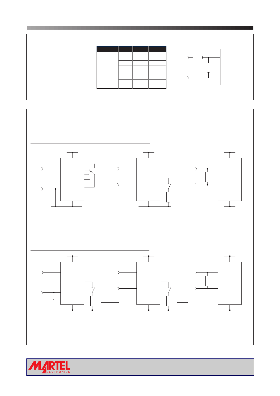
SCALING
Two external resistors Ra
and Rb may be used to
alter the full scale reading
(FSR) of the meter - see
table. The meter will have
to be re-calibrated by
adjusting the calibration
potentiometer on the rear
of the module.
FSR
Ra
Rb
2V
910k
100k
20V
1M
10k
(Vin)
200V
1M
1k
2000V*
1M
100R
200 A
0R
1k
2mA
0R
100R
( in)
20mA
0R
10R
200mA
0R
1R
µ
I
Voltage
Current
+
-
Ra
Rb
INHI
Vin or in
I
INLO
DPM 1AS-BL
*Ensure that Ra is rated for high voltage use.
5V supply operation
(3.0 to 7.5V Meter Power Supply)
9V supply operation
(6.0 to 15.0V Meter Power Supply)
+3.0 to +7.5V
+3.0 to +7.5V
-3.0 to -7.5V
+3.0 to +7.5V
+6.0 to +15.0V
+3.0 to +7.5V
+6.0 to +15.0V
V+
V+
INHI
INHI
INLO
INLO
0V
GND
V-
+
+
-
-
±200mV
2
3
3
3
2
2
1
1
1
1
1
1
5
7
9
10
8
5
5
4
4
5
5
5
6
6
6
6
6
6
±200mV
Measuring a single ended input
voltage referenced to supply, i.e. the
input voltage and the meter's power
supply share the same 0V rail.
Ensure solder link LCOM is open.
Measuring a single ended input
voltage referenced to supply, i.e. the
input voltage and the meter's power
supply share the same 0V rail.
Ensure solder link LCOM is open.
V+
V+
V+
V+
INHI
INHI
INHI
INHI
INLO
INLO
INLO
INLO
0V
0V
GND
V-
GND
V-
+
+
-
-
±200mV
±200mV
Measuring a current from a circuit which is
floating with respect to the DPM's supply,
i.e. the current and the meter's power
supply are isolated from each other.
Ensure solder link LCOM is closed.
Measuring a current from a circuit which is
floating with respect to the DPM's supply,
i.e. the current and the meter's power
supply are isolated from each other.
Ensure solder link LCOM is closed.
Measuring an input voltage referenced to
a floating supply, i.e. the input voltage
and the meter's power supply are isolated
from each other.
Ensure solder link LCOM is closed.
Measuring an input voltage referenced to
a floating supply, i.e. the input voltage
and the meter's power supply are isolated
from each other.
Ensure solder link LCOM is closed.
Rb
0V
BL-
DP1
No DP
DP2
DP3
XDP
0V
BL-
Rb
I
+
I
+
I-
I-
Rs=(V+ - 5V)
0.015
4
BL-
Rs=(V+) - (V-) - 5V
0.015
if V+>5V then
Rs=(V+ - 5V)
0.015
www.martelmeters.com
page 4 of 4