Martel Electronics DPM 2AS-BL User Manual
Dpm 2as-bl, Product description, Features
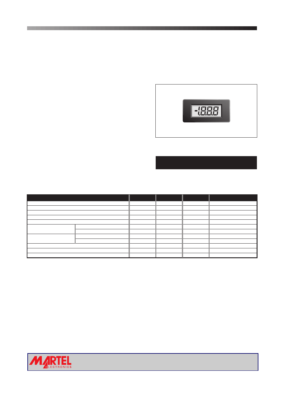
PRODUCT DESCRIPTION
The DPM 2AS-BL features a 200mV d.c. measurement range with auto-zero and auto-polarity. Decimal points are user
selectable.
LED backlighting ensures excellent readability under low light conditions.
easily snapped into a panel. The module's
The DPM 2AS-BL features a negative rail generator which enables the meter to measure a signal referenced
to its own power supply GND.
The design
of the panel meter's housing allows the module to be
low cost means it will
suit high and low volume applications. The DPM 2AS-BL is intended to replace the DPM 2, DPM 2S, DPM 2-BL and
DPM 2S-BL in many applications, usually requiring only minor circuit modifications.
FEATURES
• 8.25
• 200mV d.c. Full Scale Reading
• 3.0 to 7.5V or 6.0 to 15.0V Operation
•
•
•
mm (0.32") Digit Height
Programmable Decimal Points
LED Backlighting
Auto-zero and Auto-polarity
TYPICAL APPLICATIONS
• Precision Instrumentation Systems
• Power Supply Monitoring
• Hand held instruments
• Panel-Mount Indication
• Low Power Voltage Measurement
ORDERING INFORMATION
Stock Number
Standard Meter
DPM 2AS-BL
DPM 2AS-BL
3½ Digit Backlit LCD Voltmeter Module
SAFETY
To comply with the Low Voltage Directive (LVD 93/68/EEC), input voltages to the module’s pins must not exceed
60Vdc. The user must ensure that the incorporation of the panel meter into the user’s equipment conforms to the
relevant sections of BS EN 61010 (Safety Requirements for Electrical Equipment for Measuring, Control and
Laboratory Use).
Page 2 of 4
Page 2 of 4
ELECTRICAL SPECIFICATIONS
Specification
Min.
Typ.
Max.
Unit
Accuracy (overall error) *
0.1
% (±1 count)
Linearity
±1
count
Sample rate
2.5
samples/sec
Operating temperature range
0
50
°C
Temperature stability
250
ppm/°C
Meter supply voltage
V+ to GND configuration
3.0
5.0
7.5
V d.c.
175
A
Backlight supply voltage
4.75
5.0
***
V d.c.
Backlight supply current @ 5V d.c.
15
30****
mA
Input leakage current (Vin = 0V)
1
10
pA
* To ensure maximum accuracy, re-calibrate periodically.
** Operation of the meter beyond the maximum supply voltage rating may cause permanent damage to the meter.
*** An external series resistor is required above 5V, see Applications.
**** This specification linearly derates to 20mA @ 50°C.
V+ to V-
configuration
6.0
9.0
15.0**
V d.c.
Meter supply current
V+ to GND configuration
350
A
V+ to V-
configuration
µ
µ
Unless otherwise noted, specifications apply at T =25°C, V
=5Vd.c. (f =48kHz) and are tested with the module configured for single ended
input mode.
A
supply
clock
www.martelmeters.com
page 1 of 4