Dpm 3as-bl, Circuit diagram pin functions, 3‰ digit backlit lcd voltmeter module – Martel Electronics DPM 3AS-BL User Manual
Page 3
DPM 3AS-BL
3‰ Digit Backlit LCD Voltmeter Module
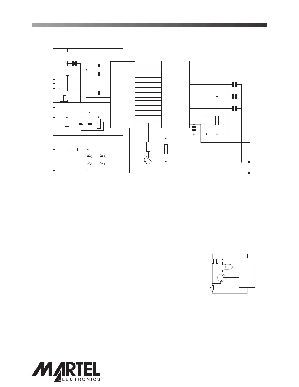
CIRCUIT DIAGRAM
PIN FUNCTIONS
www.lascarelectronics.com
1.
V-
Negative power supply to the meter (6.0 to 15.0V meter power supply applications only).
2.
INLO
Negative measuring input.
3.
INHI
Positive measuring input.
4.
COM
Ground for the analogue section of the A/D converter. It is actively held at 3.05V (nom.) below V+ and must not be
allowed to sink excessive current (>100 A) by, for instance, connecting to a higher voltage.
5.
REF LO
Negative input for reference voltage.
6.
REF HI
Positive input for reference voltage.
7.
GND
0V power supply to the meter (3.0 to 7.5V meter power supply applications only).
8.
V+
Positive power supply to the meter.
9.
TEST
Connect to V+ to test the LCD. Do not connect to V+ for more than a few seconds as this may damage the LCD.
TEST is held actively at 5V (nom.) below V+ and is the ground for the digital section of the meter. It can be used to
power external logic up to a maximum of 1mA.
10.
XDP
Inversion of LCD drive voltage.
11.
BAT
Low Battery annunciator drive pin. See application on the right.
This pin is not fitted as standard.
12.
L-
Negative power supply to LED backlighting.
13.
L+
Positive power supply to LED backlighting.
The backlighting is internally configured for 5V operation.
If a higher voltage is used, then add a series current limiting resistor Rs.
See Applications for calculations of Rs.
A negative supply is generated internally and mirrors the positive supply. For example: if V+ is +5V,then the internally generated V-
is -5V. When measuring with the input referenced to the same supply rail as that of the panel meter, then the limitations on the input
range are (V- + 1.5V) to (V+ - 1.5V).
LREF
Normally Closed. Enables the internal voltage reference circuit. Cut this link when using an external voltage reference.
BAT
Normally Open. Disables the Low Battery warning annunciator. Cut this link and add a low battery detection circuit
to enable the Low Battery warning annunciator via Pin 11 (BAT).
DP1
Normally Open. Close this solder link to enable decimal point DP1.
DP2
Normally Open. Close this solder link to enable decimal point DP2.
DP3
Normally Open. Close this solder link to enable decimal point DP3.
m
Note:
Solder Links:
V+
8
3
2
4
6
5
7
1
13
12
INHI
INLO
COM
REF HI
REF LO
GND
V-
L+
L-
INT
V+
V- TEST
a1
a1
27
1
26
28
29
31
30
32
34
36
35
33
d1
d1
e1
e1
f1
f1
DP1
199.9
DP2
19.99
DP3
1.999
g1
g1
f2
f2
a2
a2
g2
g2
e3
e3
b2
b2
a3
a3
f3
f3
c2
c2
b3
b3
g3
g3
d2
d2
c3
c3
ab
ab
e2
e2
d3
d3
b1
b1
c1
c1
5
2
8
6
7
13
12
25
18
11
23
17
10
16
22
9
24
19
14
15
4
3
BUF
A/Z
IN HI
IN LO
COM
CREF+
CREF-
REF HI
IC1
REF LO
LCD1
R4
R11
LED1
LED2
180k
22R
47pF
1u5
1u5
C5
C7
C6
C4
100nF
C1
47nF
R1
180k
C2
220nF
LREF
DP1
DP2
DP3
BAT
R10
100k
R9
3k
R3
1.5k
37
POL
POL
BP
COM
20
21
40
39
38
OSC3
OSC2
OSC1
10
11
9
V+
XDP
BAT
LOBAT
TEST
R8
1M
R5
100k
R2
1M
Q1
BCX19
R7
1M
R6
1M
Check Link BAT is OPEN.
V+
V+
XDP
BAT
TEST
8
10
1
V-
1M
470k
1M
4077
11
9
SET
BC 237
THRESHOLD
PO Box 770, Londonderry, NH 03053 1-800-821-0023
www.martelcorp.com