Wire connections and screw terminal functions, Scaling and calibration, Applications – Martel Electronics QM140V User Manual
Page 2: Required f.s.r. ra rb cal
Adding a calibration circuit when T/BLK-4 is not used
Note: The calibration circuit must always
be fitted, even when scaling resistors are
not fitted. This circuit is fitted as standard
on T/BLK-4.
100k
3k
1k5
R
CAL
V+
(Red/2)
Vref
COM
(Orange/3)
(Brown/1)
WIRE CONNECTIONS
and SCREW TERMINAL FUNCTIONS
(EMV 1125)
(T.BLK-4)
0.
Black (BK)
V-
Negative power supply connection.
1.
Brown (BR)
COM
The ground for the analogue section of the A/D converter, held actively at 2.8V (nom.) below V+.
COM must not be allowed to sink excessive current (>100 A) by connecting it directly to a higher voltage.
Positive power supply connection.
3.
Orange (OR) Vref
Connection for calibration circuit (see diagram below).
4.
Yellow (YL)
IN HI
Positive measuring differential input.
IN HI and IN LO must be no closer than 1V to either the positive or negative supply.
5.
Green (GN)
IN LO
Negative measuring differential input. (On T/BLK-4, IN LO is connected to COM via normally-closed Link L2.)
6.
Blue (BL)
DP COM Common connection for decimal points DP1, DP2 and DP3, see below.
µ
2.
Red (RD)
V+
7.
Violet (VI)
DP1
199.9
8.
Grey (GY)
DP2
19.99
Connect to DP COM to display required decimal point.
9.
White (WT)
DP3
1.999
(or make appropriate solder link on T/BLK-4)
Do not connect more than one meter to the same power supply if the meters cannot use the same signal ground. Taking any input beyond the power supply rails
will damage the meter. Keep leads short to ensure noise-free operation.
Specifications liable to change without prior warning
EMV 1125
Issue 3
January/2001
M.C.
Applies to EMV 1125/2
Required F.S.R.
Ra
Rb
CAL
200mV
N/A
N/A
Adjust
2V
910k
100k
20V
1M
10k
200 A
0R
1k
2mA
0R
100R
20mA
0R
10R
Ad
200mA
0R
1R
Adjust
Adjust
Adjust
Adjust
just
Adjust
µ
SCALING and CALIBRATION
A calibration circuit and two resistors (Ra and Rb) may be added on the
EMV 1125 or T/BLK-4 board (cut Link La if fitting Ra) to alter the full
scale reading of the meter - see table. Note that the meter will have to
be (re-)calibrated by adjusting the potentiometer.
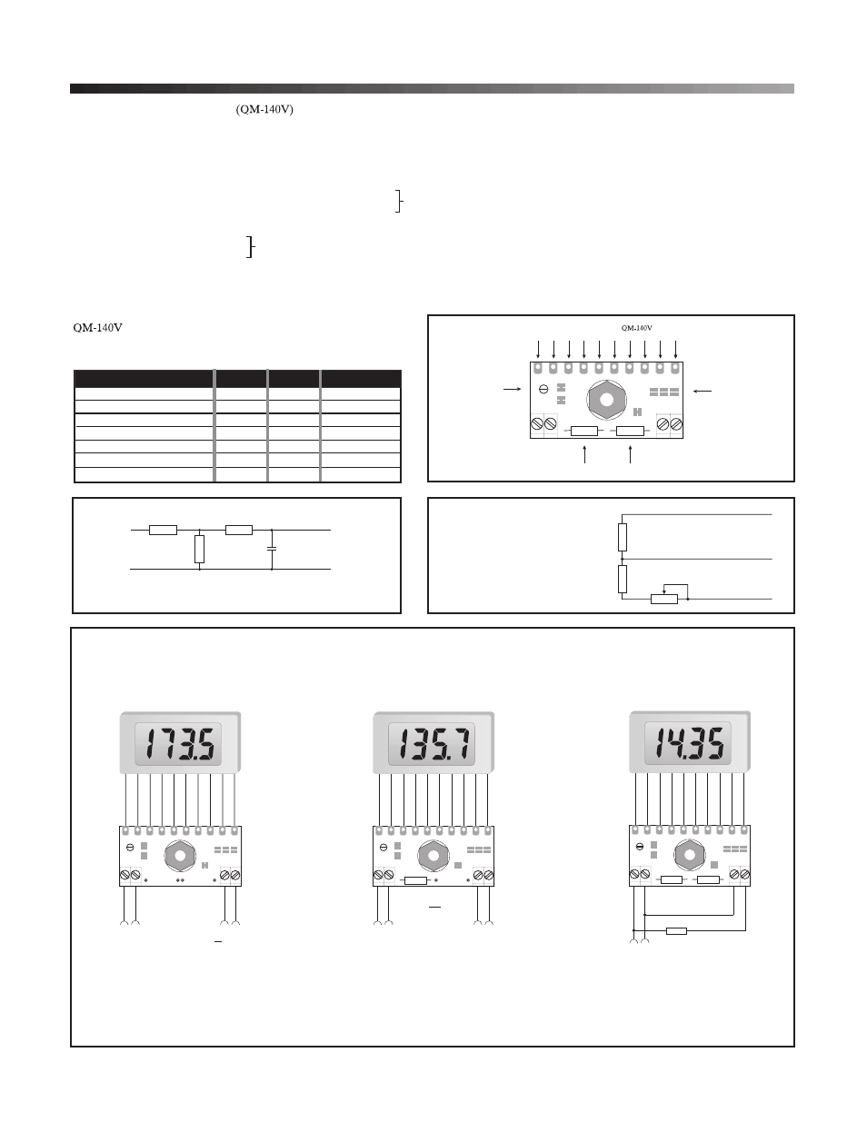
APPLICATIONS
INPUT
+
-
Ra
100k
Rb
IN HI
(Yellow/4)
IN LO
(Green/5)
Adding an input filter and scaling resistors when T/BLK-4 is not used
100nF
Note: To reduce noise on the meter's input, fit the input filter components (1M
and 10nF) shown above. The input filter is fitted as standard on T/BLK-4.
1
CAL
Rb
V- V+
INHI
INL
O
Ra
La
L1
L2
1 2 3
DP
BK BR RD OR YL GN BL VI GY WT
Solder wires from EMV 1125
Calibration
potentiometer
Scaling resistors (values for 2V and 20V FSD Supplied with T/BLK-4)
Decimal point
links
Connecting to T/BLK-4
Measuring current.
Recalibrate the module.
The current to be measured must be
isolated from the module's power supply.
Rb =
I
0.2
Full Scale
+
+
-
-
Supply
Voltage
Current to be
measured
1
CAL
Rb
V- V+
INHI
INL
O
Ra
La
L1
L2
1 2 3
DP
BK BR RD OR YLGN BL VI GY WT
+
-
Supply
Voltage
1
CAL
Rb
V- V+
INHI
INL
O
Ra
La
L1
L2
1 2 3
DP
GN BL VI GY WT
Measuring a supply voltage.
(min. 7.5V, max. 15V)
Cut Links La and L2.
Recalibrate the module.
510k
510k
10k
Measuring a floating voltage
source of 200mV full scale.
Add Ra and Rb and cut Link La to
increase the measurement range.
+
+
-
-
Supply
Voltage
+200mV
Input Voltage
1
CAL
Rb
V- V+
INHI
INL
O
Ra
La
L1
L2
1 2 3
DP
BK BR RD OR YLGN BL VI GY WT
BK BR RD OR YL
LASCAR ELECTRONICS LTD.
LASCAR ELECTRONICS INC.
MODULE HOUSE, WHITEPARISH,
PO BOX 50727, PALO ALTO,
WILTSHIRE. SP5 2SJ
UK
CA 94303-0727
USA
TEL: ++44 (1794) 884567
F
TEL: ++1 (650) 838 9027
AX: ++44 (1794) 884616
FAX: ++1 (650) 833 5432