Aviom16/o-y1, Dip switch, A-net out – Aviom 16/O-Y1 User Manual
Page 9: Stereo link switches, Stereo link mode, Made in usa
expansion port to expose the expansion connections.
• Remove the Y1 card from its protective anti-static
sleeve.
• Slide the Y1 card into place, aligning the sides of the
card with the support guides in the expansion slot.
• Press the Y1 card firmly in place to attach the multi-
pin card connectors on the Y1 card and Yamaha mixer.
• Attach the Y1 card permanently by tightening the two
thumb screws on the rear panel of the Y1 card.
N
ote
: Aviom suggests using Category 5e (or better) cables when
making A-Net connections.
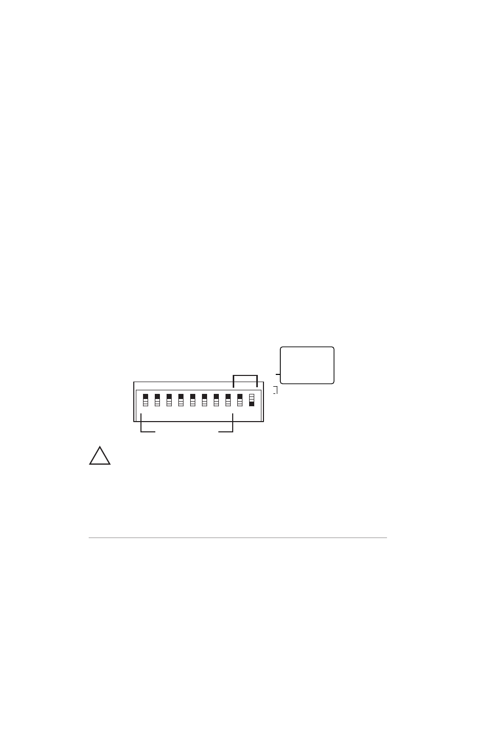
DIP Switch
The 10-position DIP switch provides two separate functions. The first
eight switches are used for controlling the stereo link status of the
eight possible audio channel pairs. The last two switches (labeled 9
and 10) provide mode selection control for the Y1 card operation.
Stereo Link
Mode
1 2 3 4 5 6 7 8 9 10
Made in USA
AVIOM16/o-Y1
A-Net Out
Stereo Link
Mode
Dn/Up - Aviom
Up/Dn - 16 ch
Up/Up - 8 ch
Dn/Dn - Test
1
2
3
4
5
6
7
8
9
10
!
The DIP switch handles shown in the diagrams in this document
are illustrated in white. (In the diagram above, for example, switch #10 is in
the up position.)
Stereo Link Switches
Positions 1 to 8 of the DIP switch are used for the stereo link function.
Stereo linking is possible when using Aviom’s Pro16 Personal Mixers
for stereo monitoring. Each switch controls a pair of channels; see the
list below. When the switch is set to the “On” position (down), the
channels are linked as a stereo pair. If the switch is in the “Off “ (up)
position, the channels are not linked.
Stereo link changes can be made at any time. All connected A-Net
devices will instantly update and reflect the change. Compatible
A-Net devices that do not respond to stereo linking will not be
affected by changes to the link status.