Lake Monitors ClearView+ Flow Meter (Polysulphone) User Manual
Page 3
Basic Application Information
The flow meter can be installed directly in the fluid line without flow
straighteners or special piping. The meter is used to measure the flow
rate of most liquids which do not contain particles greater than 74 micron.
1) The casing and union retainers are made of either Polycarbonate
or Polysulphone materials permitting use with a variety of media.
Use of mild detergent to clean the meter body is encouraged to
prevent damaging the label or associated components.
2) The meter may be mounted in the most convenient location, in any
orientation to allow easy access for reading and maintenance.
3) The ClearView
™
meter should NOT be mounted near hot pipes or
equipment which can cause damage to the pressure vessel.
4) The ClearView
™
meter should not be mounted in a manner such
that piping misalignment or other system components can exert
force or produce a bending moment on the pressure vessel.
5) To retain accuracy and repeatability internal moving parts are
closely toleranced and require filtration of at least 74 micron or a
200 mesh screen.
(3)
tubular, with all internal wetted parts sealed within the body casing
(5). Running through the center of the body casing is a tapered center
shaft which is centered in the bore. Encircling the shaft is a sharp-
edged, floating metering poppet (6). The metering poppet is held in
the “no flow” position by the biased return spring (4). As the flow
moves through the meter it creates a pressure differential across the
floating orifice disk, forcing the disk and transfer magnet against the
return spring. As flow increases, the pressure differential across the
metering poppet increases, forcing poppet to move along the tapered
center shaft. As flow decreases, the biased return spring forces the
poppet down the tapered center shaft, returning to the “no flow” position.
Reading the Meter
Notice the black reference line which runs 360° around the metering
poppet. This reference line moves under the scale in direct relation to
the movement of the poppet. When fluid is flowing, the flow rate
through the meter is read by lining up the black reference line with
the closest rate line on the flow scale.
Specific Gravity or Density Effect
Standard meters are calibrated for either WATER with a specific gravity of
1.0 or OIL with a specific gravity of .873. The floating disk meter is
affected by fluid density as are most other similar type meters. Lake’s
meters have less of this effect because of the sharpness of the floating
orifice disks being used. The indicated flow reading will read high for
heavier fluids and low for lighter fluids. A corrective factor can be applied
to the standard scale or a special scale can be added at a slight
additional costs. When measuring fluids with other specific gravities, the
basic equations below can be used to develop corrected readings.
(6)
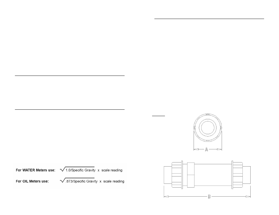
Figure 1:
Mechanical Dimensions