Reading the meter, Specific gravity or density effect, Illustration 1 – Lake Monitors Case Drain Monitor User Manual
Page 8
1.
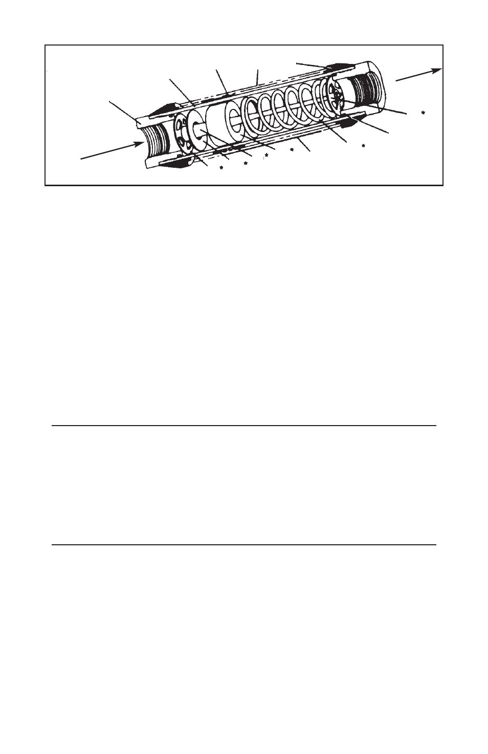
End Porting
8.
Flowing Sharp-Edged Orifice Disk
2.
Body Casing
9.
Tapered Center Shaft
3.
Magnet Follower
10. Transfer Magnet
4.
Window Tube
11. Scale
5.
Window Seal
12. Return Spring
6.
Seal Assembly
13. Retainer Ring
7.
Pilot Disk
* Cartridge contains: 7, 8, 9, 10, 12 & 13
Reading the Meter
Notice the black reference line which runs 360° around the white
magnetic follower. This reference line moves under the scale in direct
relation to the movement of the internal orifice disk. When fluid is
flowing, the flow rate through the meter is read by lining up the black
reference line with the closest rate line on the external flow scale.
Specific Gravity or Density Effect
Standard meters are calibrated for either WATER with a specific
gravity of 1.0 or OIL with a specific gravity of .873. The floating disk
meter is effected by fluid density as are most other similar type
meters. Lake’s meters have less of this effect because of the sharp-
ness of the floating orifice disks being used.
(8)
12
11
10
8
7
9
13
6
5
4
3
2
1
Flow
Direction
Flow
Direction
FLOW METER
(CROSS SECTION)
Illustration 1