Lake Monitors Case Drain Monitor User Manual
Page 11
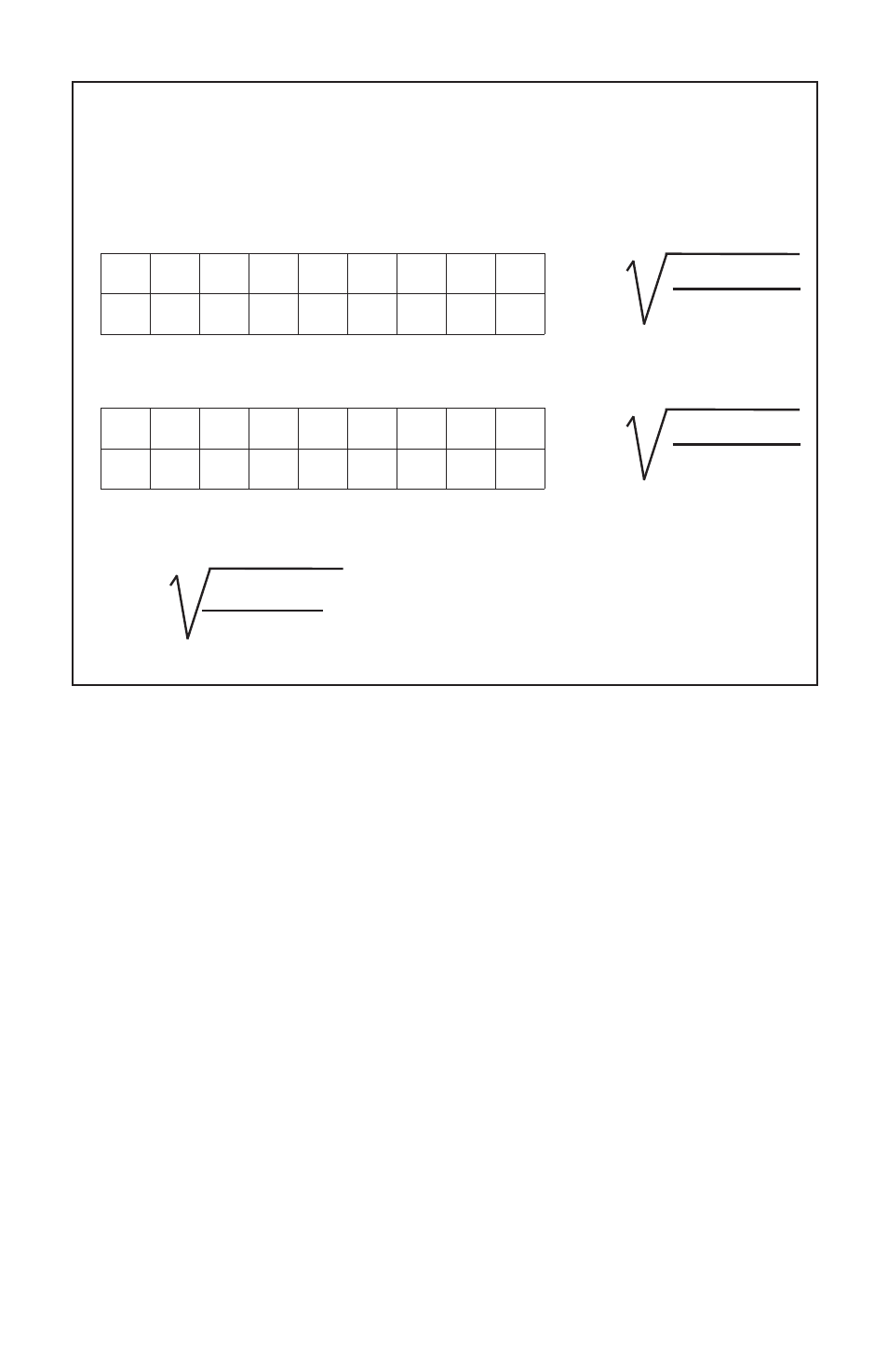
DENSITY CORRECTION FACTORS
SCFM (indicated) x (CF) = SCFM (Actual) CF= (F1) x (F2) X (F3)
Note: all correction factors need not be used.
Table 1. (f1) PRESSURE CORRECTION FACTORS (inlet pressure)
Table 2. (f2) TEMPERATURE CORRECTION FACTORS
Table 3. (f3) SPECIFIC GRAVITY CORRECTION FACTOR
f1= correction factor for other than 100 PSI inlet.
f2= correction factor for other than 70ºF.
f3= correction factor for other than air at 1.0 Sp. Gr.
Correction Factors
If a Lake meter is installed in a system where conditions differ from
the standard listed above, correction factors will need to be applied to
retain the design accuracy of the meter. The appropriate correction
factor equations are detailed above. To assure the best monitoring
accuracy, pressure and temperature measurements should be taken
directly at the meter’s inlet port.
Special Scales
Special calibrations can be performed by Lake Monitors to correct for
the following system characteristics:
system pressure
system temperature
media specific gravity
various measuring units (i.e. LPM, LPS, m3/hr, etc.)
any combination of the above
Consult Lake’s factory or your distributor for details and prices.
(11)
psig
25
50
75
100 125 150 175 200
f1
.56
.75
.88
1.0 1.11 1.2 1.29 1.37
ºF
10º
30º
50º
70º 90º 110º 130º 150º
f2 1.08 1.04 1.02 1.0 .98 .96 .95 .93
f1 =
14.7 + psig
114.7
f2 =
530
460 + ºF
f3 =
1
Sp. Gr.